Once the volume has been loaded it may be necessary to change the orientation of the volume to match the application’s normal camera orientation or to be consistent with other geometry in the scene. For example if we loaded the sample volume “3DHead.ldm” instead of the “3DHead.vol”, the resulting image would look like this:
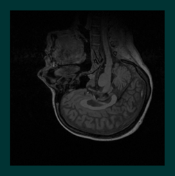
Notice that the native orientation of this particular data set is “upside down” with respect to the default Open Inventor coordinate system. This, or other orientation problems, are easily corrected but to understand this result we need to understand the way VolumeViz loads data. The standard VolumeViz readers load the data values (voxels) in a volume sequentially, incrementing X, then Y, then Z. This is the fastest way to load the data and corresponds to the way data is typically organized for medical images. In other words, the X axis is the “width” of a single slice, the Y axis is the “height” of a single slice and slices in the stack are loaded “back to front” along the Z axis. Of course this organization is not appropriate for all data volumes. One option is to reorganize the data during the conversion to LDM format. We will discuss LDM conversion in Section 1.2.6, “Converting to LDM”. Orienting SEGY volumes will be discussed in a later section. This example data set allows us to illustrate that the volume visualization primitives are treated as “geometry” in most respects and therefore can be rotated as in any Open Inventor application.
As usual we have the choice of rotating the geometry in the scene, using a transform node, or rotating the camera to a different orientation. Which choice is better depends on the application, in particular on the orientation of other geometry that may be needed in the scene. In both cases we will apply a rotation of pi radians (180 degrees) around the Z axis. The following (standard Open Inventor) code will rotate the geometry:
C++
SoTransform* pTransform = new SoTransform;
pTransform->rotation = SbRotation( SbVec3f(0,0,1), (float)M_PI );
pRoot->addChild( pTransform );
.NET
SoTransform Transform = new SoTransform();
Transform.rotation.Value = new SbRotation(new SbVec3f(0, 0, 1), (float)Math.PI);
Root.AddChild( Transform );
Java
SoTransform transform = new SoTransform();
Transform.rotation.setValue( new SbRotation(new SbVec3f(0, 0, 1), (float)Math.PI) );
Root.AddChild( Transform );
The following code will rotate the camera:
C++
SoCamera* pCamera = pViewer->getCamera();
pCamera->orientation = SbRotation( SbVec3f(0,0,1), (float)M_PI );
.NET
SoCamera Camera = Viewer.GetCamera();
Camera.orientation.Value = new SbRotation(new SbVec3f(0, 0, 1), (float)Math.PI)
Java
SoPerspectiveCamera camera = new SoPerspectiveCamera();
camera.orientation.setValue( new SbRotation(new SbVec3f(0, 0, 1), (float)Math.PI) );
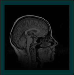
Resulting image:
![[Important]](../../images/important.jpg) | |
Note: The volume size and orientation (like geometry) can be modified by transformation nodes in the scene graph and this in turn modifies the appearance of volume rendering nodes like SoOrthoSlice( C++ | Java | .NET ). However the same transformation must be applied to the volume data node and all volume rendering nodes associated with that volume. So effectively any transformation nodes that affect the volume must be placed before the volume data node. |