VolumeViz supports clipping the volume against any closed 3D polygonal shape defined by standard Open Inventor geometry. This is done using the SoVolumeClippingGroup SoVolumeClippingGroup SoVolumeClippingGroup node. Polygon clipping can remove the voxels outside the shape or the voxels inside the shape. Polygon clipping can be used in seismic applications to clip outside a fault block or geobody, in medical applications to cut away an arbitrary region, in core sample applications to apply cylindrical clipping and many other uses.
When an SoVolumeClippingGroup SoVolumeClippingGroup SoVolumeClippingGroup is in the scene graph before a VolumeViz rendering node, all shapes under the SoVolumeClippingGroup SoVolumeClippingGroup SoVolumeClippingGroup will be used to clip the volume. These shapes will not be displayed.
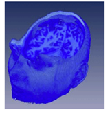
The images below show the result (right) of clipping the volume (left) against a sphere (middle).
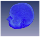 |
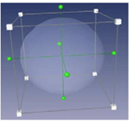 |
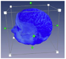 |
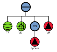
The following figure shows the corresponding scene graph, where CG is an SoVolumeClippingGroup SoVolumeClippingGroup SoVolumeClippingGroup .
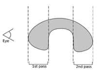
The numPasses field allows you to increase the clipping quality when using shapes with a lot of concavity (see figure bellow). To query the maximum allowed number of passes, which depends on your graphics card, use the static method SoVolumeClippingGroup SoVolumeClippingGroup SoVolumeClippingGroup ::getMaxNumPasses().
Each time a part of the object is hidden by another part of the shape, numPasses must be increased. With the shape shown above, numPasses should be set to two for the best rendering.
When the clipOutside field is set to FALSE, the parts of the volume which are outside of the clipping shape are displayed. The default is TRUE.
Very complex shapes can be created by combining simpler polygonal shapes. The SoCSGShape SoCSGShape SoCSGShape node is very useful for this purpose. SoCSGShape SoCSGShape SoCSGShape applies a Constructive Solid Geometry (CSG) operation to a pair of scene graphs containing polygonal geometry. These operations include add (union), subtract and intersection. One or both of the scene graphs can be another CSG shape node, creating a tree of input shapes. If the topmost CSG shape node is then put under an SoVolumeClippingGroup SoVolumeClippingGroup SoVolumeClippingGroup node the volume will be clipped against the final result of the specified CSG operations.
Applications implementing interactive volume sculpting, for example seismic applications for geobody extraction, may also find the SoScreenDrawer SoScreenDrawer SoScreenDrawer classes useful. These classes are related to draggers. Specifically they provide a platform independent way to allow the user to "draw" on the screen using a rectangle, ellipse, polygon or lasso. For example SoLassoScreenDrawer SoLassoScreenDrawer SoLassoScreenDrawer allows the user to free-hand draw a 2D shape on the shape then returns the points to the application at the end of the operation. The application can then use the utility class SbExtrusionGenerator SbExtrusionGenerator SbExtrusionGenerator to create a 3D shape by extruding the 2D outline along the current direction of view. The figure below shows an extruded polygon on the left and on the right the effect of using that shape as a clipping polygon in addition to the two clipping surfaces.
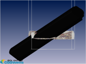 |
 |
|---|
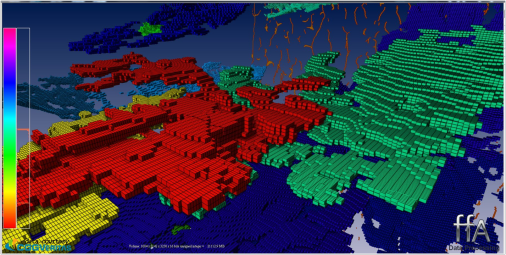
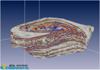
The figure below shows the final result of multiple volume sculpting operations on a large seismic volume (displayed using the voxelized rendering mode).
