Open Inventor can read the following CAD file formats:
- CATIA V5 (.catpart, .catproduct): from R7 to R23
- CATIA V6 (.3dxml): support geometry reading from R2010x to R2013x
- AutoCAD (.dwg): from v2.5 up to 2013. Converts 3d entities, mesh and wireframe
- IGES (.iges, .igs): supports release until 5.3
- JT (.jt) : Supports tessellated Jt 3d files and B-REP. Up to 9.5
- Parasolid (.xmt, .x_t, .x_b) : from v7 to v26
- To check names (PTC Creo Parametric is the Evolution of Pro/ENGINEER …) PROECREO (.asm, .prt, .xar, .xpr) : support from Pro/E 2000i to Creo Parametric 2.0
- Solid Edge (.par, .asm, .psm, .pwd) : up to ST6
- STEP (.step, .stp, .stp.Z) : Support STEP protocols from AP203 (Edition 1 and 2), AP214 (up to Edition 3), AP242 (Edition pre-DIS)
- UG NX: from v10 to 2014 (file extension )
- SOLIDWORKS: support version from 1999 to 2014
- VDA (.vda)
- Unigraphics (Ug) In order to read these files, you need to acquire a license of the appropriate CAD format from FEI and to install it on your system.
When importing one of these files, part names will be imported too. But you must keep in mind than as long as they are imported directly into nodes, the Open Inventor node name limitations will be directly applied. Those limitations can be found in documentation of SoBase::setName() method. The main thing to remember is that any unsupported character is automatically replaced by an underscore ‘ _ ‘ .
Import customization
The import of a CAD file can be customized with parameters exposed in the SoCADInputReaderParameters class.
Tessellation Parameters
Open Inventor allows customer to change the quality of tessellation performed during import. For these, two API are available. The simplest one is to use directly the setTessellationOption (Quality quality = MEDIUM) allowing to specify predefined tessellation options. Quality has to be chosen from SoCADInputReaderParameters::LOW, SoCADInputReaderParameters::MEDIUM, SoCADInputReaderParameters::HIGH. Logically the better the quality is, the longer the import will be.
To go deeper into tessellation customization the API provides an inner struct, called TessellationOption that allows defining
- The maximum distance between tessellated mesh and the original surface. This option is set via the linearTolerance variable of the structure. A value of 0.0 means the feature is deactivated. Smaller value means more precise tessellation but more memory consumption. Default value is 0.5.
- The maximum deviation between tessellated mesh and the original surface. This option is set via the angularTolerance variable of the structure. Smaller value means more precise tessellation but more memory consumption. Default value is 0.0.
- The maximum edges length ratio of generated triangles. This option is set via the maxTriangleEgesRatio variable of the structure. The smaller value is 1.0 giving a more precise tessellation but, as usual, with more memory consumption. Default value is 20.0. . Once the option has been defined, the application may set the options using the method setTessellationOption (const TessellationOption& option)
Import option
Among the tessellation options, application can also customize which entities of a CAD file are needed to be imported and which don’t, allowing reducing import time. These options are set via the SoCadReaderInputParameters::ImportOption struct defined in the SoCADInputReaderParameters class and propose following API:
- importEdges: import or not edges for the model (default is false)
- importOpenShells: import or not open hells for the model (default is false)
- importPMI: import or not Product and Manufacturing Information for the model (default is false)
- mergeFaces: decide if imported geometry must be merged in a single Open Inventor geometry object (default is false). Options have then to be set using the SoCADInputReaderParameters::setImportOption(const ImportOption& option) methods and the import can be made.
Structure of the generated scene graph
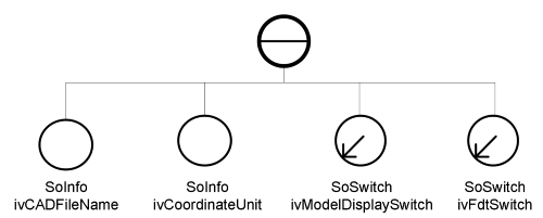
In order to keep things as clear as possible, the import of a CAD file into Open Inventor generates a well-structured scene graph in which the user can retrieve all the needed information.
- Multi views When importing CAD file supporting multi views, Open Inventor will generate a particular sub scene graph to store information about each view. In the generated scene graph a special switch named ivModelDisplaySwitch will always be at the top of all the views defined in the original file. Changing the field whichChild of this node will change the current view rendered in the viewer. Here are some simple code examples to manipulate the switch managing the multi-view in the Open Inventor scene graph.
Example : Retrieve ivModelDisplaySwitch
SoSearchAction* searchAction = new SoSearchAction;
searchAction->setFind( SoSearchAction::NAME );
searchAction->setSearchingAll( true );
searchAction->setType( SoSwitch::getClassTypeId() );
searchAction->setName( "ivModelDisplaySwitch" );
searchAction->apply( scene );
SoPath* path = searchAction->getPath();
SoSwitch* ivModelDisplaySwitch = NULL;
if ( path )
ivModelDisplaySwitch = dynamic_cast<SoSwitch\*>( path->getTail() );
delete sa;
Example : Changing view from SoEventCallBack
// Assume the ivModelDisplaySwitch node has been retrieved before
if ( ivModelDisplaySwitch && ivModelDisplaySwitch->getNumChildren() > 0 )
{
int curChild = ivModelDisplaySwitch->whichChild.getValue();
int maxChild = ivModelDisplaySwitch->getNumChildren();
// Use PAGE_UP to select next view. Loop over view in case
// we reach the last one
if ( SO_KEY_PRESS_EVENT( ev, PAGE_UP ) )
{
if ( curChild + 1 != maxChild )
ivModelDisplaySwitch->whichChild.setValue( curChild + 1 );
else
ivModelDisplaySwitch->whichChild.setValue( 0 );
eventCB->setHandled();
}
// Use PAGE_DOWN to select previous view. Loop over view in case
// we reached the first one
else if ( SO_KEY_PRESS_EVENT( ev, PAGE_DOWN ) )
{
if ( curChild > 0 )
ivModelDisplaySwitch->whichChild.setValue( curChild - 1 );
else
ivModelDisplaySwitch->whichChild.setValue( maxChild - 1 );
eventCB->setHandled();
}
else if ( SO_KEY_PRESS_EVENT( ev, O ) )
{
ivModelDisplaySwitch->whichChild.setValue( 0 );
eventCB->setHandled();
}
// Then in all case update the viewer's camera by searching the SoCamera
// on select child.
if ( SO_KEY_PRESS_EVENT( ev, O ) || SO_KEY_PRESS_EVENT( ev, PAGE_DOWN ) || SO_KEY_PRESS_EVENT( ev, PAGE_UP ) )
{
SoCamera* newCamera = SearchCameraFrom( ivModelDisplaySwitch->getChild( ivModelDisplaySwitch->whichChild.getValue() ) );
if ( newCamera )
{
viewer->setCamera( newCamera );
viewer->viewAll();
}
}
}
- Product and Maintenance Information (PMI) In the same way as themultiple views, the import of a CAD file including Product and Manufacturing Information (PMI) is managed in a sub part of the main scene graph of the Open Inventor scene. This sub scene graph is topped by a SoSwitch named ivFdtSwitch. Each element of the PMI is placed under this SoSwitch and will have a name prefixed with the ivFdt_ string making them easy to retrieve with a SoSearchAction.
- Multi parts As seen before, the import process allows defining which parts of the CAD file should be taken in consideration and which must not. This result is a particular structure in the generated scene graph once the file has been opened using Open Inventor. The main part of the scene graph starts under the SoMultiSwitch named ivRenderMode. This multi switch defines the list of child’s underneath SoMultiSwitch will inherit of. In other words it defines which rendering modes (Faces, edges, vertex and curves) will be done. Here is an example in a simple generated scene graph.
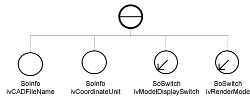 Under the main SoMultiSwitch ivRenderMode are listed, as SoSeparator, all the parts of the imported model named with Open Inventor convention and prefixed with the name of the part they belongs to.
These separators are all under a SoMultiSwitch that inherits their whichChild list from the main one. By default this main SoMultiSwitch will always set its whichChild list so the four modes are rendered, meaning the list is set to 0, 1, 2 and 3 at the top of the scene graph.
To remove the edge of the rendering (for example), we must remove child number 1 in the whichChild list of the main SoMultiSwitch so separator won’t be traversed when edges are underneath. This is a very convenient feature allowing rendering different parts of a given models in different modes very easily (the main SoMultiSwitch can be retrieved using a SoSearchAction with its very specific name)
