|
Open Inventor Release 2024.2.3
|
|

| |
|
Open Inventor Release 2024.2.3
|
|
|
| |
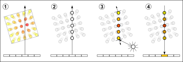
Compared to slice rendering, direct volume rendering is a completely different way of generating an image. Unlike other Open Inventor rendering nodes, volume rendering does not use any of the traditional computer graphics primitives such as points, lines or triangles. Volume data is a 3D scalar field and can be considered a regular grid of scalar valued cells. By analogy with a 2D “pixel”, the computer graphics short-hand for “picture element”, each 3D cell is called a “voxel”, which stands for “volume element”. Volume rendering is able to directly display volume data without using any geometry. VolumeViz does this using a technique called volume ray-casting. Rays are cast through the volume and sampled at regular or adaptive intervals. The data values are interpolated at each sample point. The resulting scalar value is mapped to a color and opacity through a transfer function (for example a color map) which results in an RGBA value. Conceptually this value determines how the voxel affects light passing through the volume. Considering this conceptual model, the RGBA value is composited with previous values along the ray. The final composited value of the ray determines the color of the corresponding pixel on the screen. Like other rendering nodes this algorithm is completely implemented on the GPU for maximum performance.
Volume rendering is a unique rendering technique and much more powerful than slice based rendering. However it is also much more complicated to use and generally less interactive than slice rendering because of the tremendous amount of computation needed on the GPU. While slice rendering can provide clues about the internal structure of the volume, volume rendering can directly visualize the shapes of internal structures such as bones, seismic horizons or material defects. For volumes with distinct boundaries between different regions/materials, the volume rendered image can look very similar to lighted, shaded polygonal geometry. Conversely, by appropriate assignment of color and opacity to the voxels, the volume rendered image can show deeply nested structures inside of structures simultaneously. In many ways it is convenient to think of the SoVolumeRender node as a kind of geometry node. VolumeViz applies standard Open Inventor attributes and operations as much as possible. For example you can apply lighting to voxels and voxels can both cast and receive shadows. Similarly when you apply an SoRayPickAction to a scene containing volume rendering, the action will find the point of intersection with the first non-transparent voxel.
In addition to the classical volume rendered image based on compositing voxel RGBA values, the VolumeViz ray-casting engine can also generate isosurface and “sugar cube” UserGuide_Images from the volume data. Conceptually an isosurface is a surface that represents points of a constant value (e.g. intensity, density, etc) within a data volume. Traditionally visualization of an isosurface requires a computation step (e.g. Marching Cubes) to generate polygonal geometry and every time the iso-value is changed the geometry must be re-computed. Volume rendering is able to generate a very similar image with no computation step. The “sugar cube” rendering mode produces a Lego-like effect, where the spatial extent of each voxel is represented by a box with optional edges. The color of each box is derived from the voxel value and transfer function.
VolumeViz generates volume rendered UserGuide_Images using an algorithm called volume ray casting. This algorithm implements the classic computer graphics rendering equation based on emission, reflection and absorption of light. It is an image based technique because the number of rays cast into the volume depends on the number of pixels that must be rendered on the screen. The algorithm is much more flexible than textured polygon techniques because the sampling along the rays can adapt to the data in the volume to increase performance and increase image quality. The VolumeViz ray-casting engine runs on the GPU and utilizes the massive parallelism of the GPU to deliver excellent performance that scales with the number of processors on the graphics board. The GPU implementation also allows the rendering algorithm to be extended and customized by the application using shader functions written in the standard GLSL language.
:_1__Ray_Casting_2__Sampling_3__Shading_4__Compositing_
VolumeViz also supports an older rendering algorithm for compatibility. This algorithm approximates volume rendering by drawing a stack of polygons (called slices in the documentation) that are textured with the volume data. The polygon rendering algorithm can be activated by setting the raycasting field to false in an SoVolumeRenderingQuality node.
Like the slice primitives, the color and opacity of volume rendering is primarily determined by the SoMaterial, SoDataRange and SoTransferFunction (color map) nodes described in Appearance. The appearance of volume rendering is also affected by interpolation but the options are slightly different than for slice primitives. After the basic color and opacity are determined, lighting and rendering is much more complex than slice rendering. The final appearance of volume rendering is also affected by LDM memory settings, rendering quality settings, rendering effects and rendering modes.
The appearance of volume rendering is affected by rendering quality settings ( Volume rendering quality settings) set using the SoVolumeRender or SoVolumeRenderingQuality node. These settings include:
The appearance of volume rendering can be enhanced by rendering effects ( Volume rendering effects), also set using the SoVolumeRenderingQuality node. These effects include both realistic effects like lighting and non-photorealistic (NPR) effects like edge coloring:
Volume rendering can be clipped by clip planes, region of interest (SoROI), polygon clipping (SoVolumeClippingGroup) and height field clipping (SoUniformGridClipping) as described in Clipping. By default volume rendering primitives are pickable and the volume rendering detail class allows you to query the position and value of the picked voxel.