Next you can use the set() method, a method for SoBaseKit( C++ | Java | .NET ) that is inherited by all node kits. Use the set() method to create a part and specify field values in the new node. This method has two different forms:
set(nameValuePairListString); // uses braces to separate // part names from value pairs
or
set(partNameString, parameterString); // does not use braces
An example of the first form of set(), which makes a material node and sets the diffuse color field to purple is as follows:
C++
myShape->set("material { diffuseColor 1 0 1 }");
.NET
myShape.Set("material { diffuseColor 1 0 1 }");
Java
myShape.set("material { diffuseColor 1 0 1 }");
An example of the second form of set(), which does the same thing, is as follows:
C++
myShape->set("material", "diffuseColor 1 0 1");
.NET
myShape.Set("material", "diffuseColor 1 0 1");
Java
myShape.set("material", "diffuseColor 1 0 1");
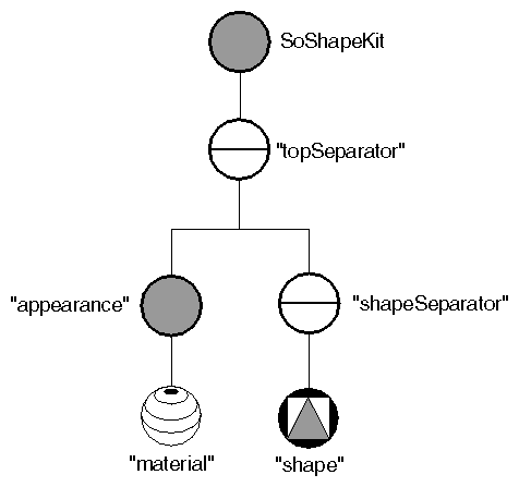
The scene graph for this instance of the shape kit now looks like Figure 16.7, “ Adding the Material Node ”. Note that the SoAppearanceKit( C++ | Java | .NET ) node is created automatically when you request the material node. Also note that the node is created only if it does not yet exist. Subsequent calls to set() edit the fields of the material node rather than recreate it.
Now suppose you want to make the cube wireframe rather than solid, and twice its original size:
C++
myShape->set("drawStyle { style LINES }
             transform { scaleFactor 2.0 2.0 2.0 } ");
.NET
myShape.Set("drawStyle { style LINES } transform { scaleFactor 2.0 2.0 2.0 } ");
Java
myShape.set("drawStyle { style LINES } transform { scaleFactor 2.0 2.0 2.0 } ");
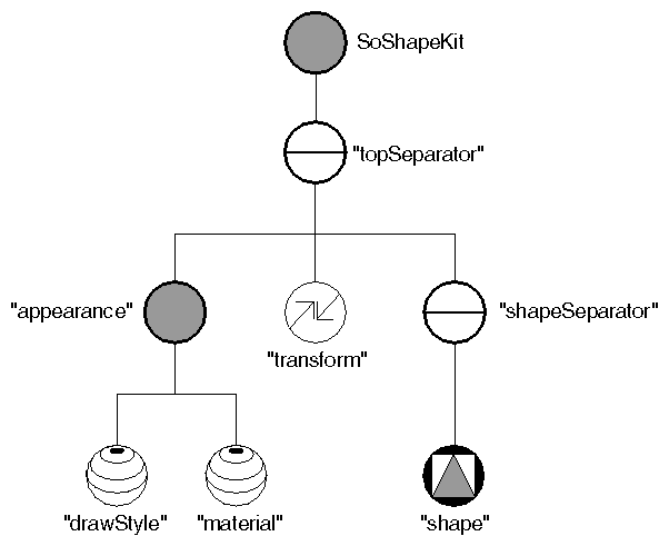
The scene graph now looks like Figure 16.8, “ Adding Draw-Style and Transform Nodes ”.
Note that you can use the set() method to create the nodes in any order. The node kit automatically inserts the nodes in their correct positions in the scene graph, as specified by the node-kit catalog.
This instance of the shape kit now contains eight nodes, as shown in Figure 16.8, “ Adding Draw-Style and Transform Nodes ”.

