To use NURBS curves and surfaces in an Inventor program, you need to develop an intuitive feel for a number of basic concepts. This section defines these key concepts and shows how they pertain to the various Inventor NURBS-related classes. For a more rigorous mathematical description of a NURBS, see Section 20.5, “Suggestions for Further Reading” at the end of this chapter.
This chapter describes use of the following classes:
represents a NURBS curve. (This is where the knot sequence is specified.) | |
represents a NURBS surface. (This is where the knot sequence is specified.) | |
trims regions from a NURBS surface using a NURBS curve. | |
trims regions from a NURBS surface using connected line segments. | |
SoProfileCoordinate2 SoProfileCoordinate2 SoProfileCoordinate2 | specifies 2D coordinates for trim curves. |
SoProfileCoordinate3 SoProfileCoordinate3 SoProfileCoordinate3 | specifies rational 2D coordinates for trim curves. |
specifies the control points of a NURBS surface or curve. | |
specifies rational control points of a NURBS surface or curve. |
For simplicity, this discussion first explains the important NURBS concepts in terms of curves, which are lines in 3D space, such as a helix. Once you understand how to define a NURBS curve, defining a NURBS surface is a simple extension of your knowledge (see Section 20.4, “NURBS Surfaces”).
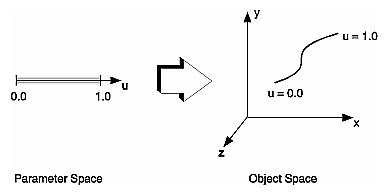
A NURBS curve or surface is parametric—that is, the equations that describe it depend on variables (or parameters) that are not explicitly part of the geometry. A NURBS curve is described in terms of one parameter, u. The following three functions map this single parameter into x-y-z space:
x = f(u)
y = g(u)
z = h(u)
By sweeping through different values of u (that is, through parameter space), it is possible to evaluate the equations and determine the x, y, and z values for points on the curve in object space. Figure 20.1, “ Mapping a Parametric Curve to Object Space ” represents this mapping of parameter space to object space.
