Caching saves the result of an operation so that it doesn't need to be repeated. Inventor provides two kinds of caching: render caching and bounding-box caching. (See Section 8.5, “Calculating a Bounding Box” for a description of the SoGetBoundingBoxAction SoGetBoundingBoxAction SoGetBoundingBoxAction .) For both the render action and the bounding-box action, you can specify that the results of the traversal be saved in a cache. The render cache, for example, contains an OpenGL display list that results from traversing the scene graph to be rendered. If the scene graph does not change, Inventor can use the contents of this cache for subsequent renderings, without traversing the scene graph at all.
AnSoSeparator SoSeparator SoSeparator node has one field that is used for caching. Possible values for these fields are AUTO, ON, or OFF. AUTO is the default value.
The caching process begins with the separator group, as follows:
If a valid cache exists, the separator group ignores the scene graph below it and uses the contents of the cache.
If a valid cache does not exist, the separator group checks the appropriate field to see if it should create a cache.
If caching is ON, it opens a cache, traverses the nodes under the separator group, records the results in the cache, and then calls the cache. If caching is AUTO, Inventor uses a special set of conditions to determine whether it is efficient to create a cache.
The nodes under the separator group may inherit values from nodes that appear before the separator group in the graph. For example, materials, coordinates, texture coordinates, complexity nodes, normals, and bindings tend to be used by each shape. If these values change, the cache needs to change. (Note that if a texture outside the cache changes, the cache is still valid because the shape does not send the texture calls to OpenGL. The texture is sent directly to OpenGL when the SoTexture2 SoTexture2 SoTexture2 node is traversed.)
Be aware that these changes also invalidate the cache:
Inventor is conservative in determining whether the current cache is valid (that is, caches may be invalidated and rebuilt even if inherited values have not changed).
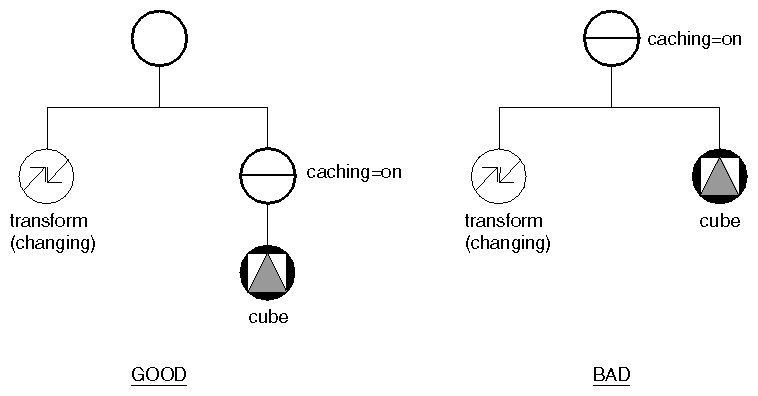
Figure 9.15, “ Caching a Shape ” shows a scene graph with a transform node whose values are changing frequently and a cube. In this case, turn on caching at the separator above the cube so that the changing transform values do not invalidate the cache.
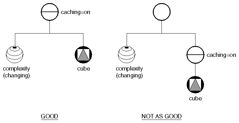
Figure 9.16, “ Caching a Shape along with a Changing Property Node ” shows a scene graph with a complexity node whose values are changing frequently and a cube. Here, you would include both the property node and the shape in the same cache, since the shape always uses the property node when it is rendered.
Render caches can consume a great deal of memory, but they are very useful for speeding up rendering. Using the AUTO (default) value for render caching allows Inventor to determine whether creating a render cache will save time.
Bounding-box caching is relatively inexpensive. Inventor uses bounding- box caching to speed up picking. If bounding-box caching is on and the user picks part of the graph that contains a separator group, the separator group can first check to see if the bounding box is picked. If not, it knows nothing under it is picked and does not need to traverse the subgraph.
If you are dealing with a large scene and you know that the camera will frequently view only part of that scene, you may want to turn on render culling so that Inventor doesn't take time rendering parts of the scene that lie completely outside the camera's view. An SoSeparator SoSeparator SoSeparator node has two flags used for culling: renderCulling and pickCulling. By default, render culling is AUTO. By default, pick culling is ON.
This description deals with render culling. (Pick culling works in a similar manner and is relatively inexpensive; you will probably simply leave it ON.) Here's a brief summary of how render culling works:
The camera puts the world-space view volume into the traversal state when it is traversed.
During traversal, the separator node tests its renderCulling field. If it is ON, it culls the render area, as follows:
It computes the bounding box for the separator, in object space. (This information may be cached already.)
It transforms the bounding-box information into world space and compares it to the view volume in the state.
If the bounding box is completely outside the current view volume, the separator does not traverse its children.
Since Step 2 (computing the bounding box and testing it) is fairly expensive in terms of time, render culling is off by default. You'll need to evaluate your scene graph to determine whether render culling will be efficient. For example, you could have a large scene graph with external walls, and detailed electrical and plumbing connections beneath them. Although the scene graph is complex, culling won't help because all elements would be in the camera's view at the same time. However, for scenes where objects are widely separated in space, such as a scene graph for a solar system, culling can be very useful.
![[Tip]](../images/tip.jpg) | |
Tip: To facilitate culling, organize the database spatially so that objects that are close to each other in 3D space are under the same separator and objects far away from each other are under different separators. In the case of the scene graph with external walls, you could group the plumbing and electrical connections for each wall under a separator. |
Guidelines for turning on render culling are as follows:
In general, don't put a culling separator underneath a caching separator.
The reason for this guideline is that culling depends on the camera. If a separator makes a culling decision, any cache that it is part of will depend on the camera. Caches dependent on the camera will often be broken, because in most applications, the camera changes frequently.
It's also efficient to turn on culling and caching at the same separator node (or turn on culling and leave caching at AUTO).
Turn on culling only for objects that are separated in space.
Turn on culling only for objects with a fairly large number of polygons, or deciding whether to cull might take longer than just drawing the object.
The SoSFBool SoSFBool SoSFBool field boundingBoxIgnoring has been added in some nodes in order to ignore the bounding box of the specified nodes. The value indicates whether the bounding box is ignored or not. It can be useful to ignore the bounding box for annotation geometry (for example color bars and legends) that should not be considered by the viewer’s “viewAll” operation. This field can also be used to suppress computation of the bounding box for very large or frequently modified geometry. However ignoring the bounding box of actual scene geometry can cause problems, for example with automatic adjustment of clip planes in the viewer. For scene geometry we recommend using the SoBBox SoBBox SoBBox node to specify a precomputed bounding box.
An effect similar to ignoring the bounding box could previously be accomplished using an SoResetTransform SoResetTransform SoResetTransform node to reset the bounding box. Using the boundingBoxIgnoring field or SoBBox SoBBox SoBBox node is more efficient because it avoids computing the bounding box.
The following nodes and all inherited nodes contain this field:
SoGroup SoGroup SoGroup : Prevents computation of the bounding box for all nodes below this one in the scene graph (SoGetBoundingBoxAction SoGetBoundingBoxAction SoGetBoundingBoxAction will not traverse below this node).
SoShape SoShape SoShape : Prevents computation of the bounding box for this shape.
SoBaseKit SoBaseKit SoBaseKit : Prevents computation of the bounding box for this nodekit.
This node allows the application to specify a bounding box for a portion of the scene graph. The main goal of this node is to avoid computing the bounding box when we already know it. Computing the bounding box for a large geometry (e.g. 1 million+ triangles) can be time consuming, especially if the geometry is changing, for example driven by an animation.
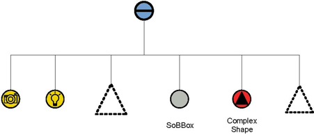
In this example the bounding box is computed in each node up to the node SoBBox SoBBox SoBBox . It is not computed for the nodes placed after the SoBBox SoBBox SoBBox node.
The mode field has three possible values:
SoBBox::DISABLE: The node is ignored by all actions. (The bounding box is computed for all the subsequent nodes of the scene-graph.)
SoBBox::NO_BOUNDING_BOX: Subsequent nodes in this part of the scene graph are treated as if they have no bounding box. SoGetBoundingBoxAction will stop traversing this part of the scene graph. This can be used to prevent some nodes from affecting the overall bounding box, as discussed in the section called “boundingBoxIgnoring field”.
SoBBox::USER_DEFINED: Subsequent nodes in this part of the scene graph are treated as if they have the bounding box specified in the boundingBox field. SoGetBoundingBoxAction SoGetBoundingBoxAction SoGetBoundingBoxAction will stop traversing this part of the scene graph and use the specified bounding box. If rendering in VIEW_BBOX mode (see the SoXXXViewer method setDrawStyle), SoBBox will draw the specified bounding box and subsequent nodes in this part of the scene graph will not be traversed.
This node is used in two demos:
$OIVHOME/src/Inventor/examples/Features/BufferObjects/AnimatedShape
$OIVHOME/src/Inventor/examples/Features/BufferObjects/SoBufferedShape
The first demo renders an animated textured shape. There is no need to compute the bounding box for each animation step because the formula is based on an amplified sin function and the bounding box is defined by the limits of the formula. The bounding box node is added just before the shape so the bounding box action will not compute a bounding box for the shape.
The second demo renders a huge geometry using an SoBufferedShape SoBufferedShape SoBufferedShape node. Computing the bounding box of this shape takes a long time because the geometry is stored directly on the graphic card. Therefore computing the bounding box requires uploading the data to system memory before computing the bounding box. But we can precompute the bounding box for this shape and set it using an SoBBox SoBBox SoBBox node. Changing the scale of the geometry triggers a scene graph traversal for the bounding box, but we can apply the same scale to the bounding box, there is no need to compute it using the geometry.
See the section called “Buffered Shape” for more information about SoBufferedShape SoBufferedShape SoBufferedShape .
The fast editing feature allows you to modify parts of a scene without redrawing the entire scene. For example, you could use it to interactively move a small object in a large scene that takes a long time to redraw. This feature takes advantage of the fact that only a small number of triangles will have to be redrawn rather than all of them.
To use fast editing, there are two steps:
You must specify to which parts of the scene you want to apply fast editing mode.
This is done by setting the SoSeparator SoSeparator SoSeparator fastEditing field to the desired value. Possible values are DISABLE, KEEP_ZBUFFER, and CLEAR_ZBUFFER. Using KEEP_ZBUFFER means that the fast edit geometry is depth buffered against the other objects in the scene, and using CLEAR_ZBUFFER means that the fast edit geometry will be drawn on top of the other objects of the scene. If several SoSeparator SoSeparator SoSeparator s have the CLEAR_ZBUFFER flag set, they are drawn in the order in which they appear in the scene. The last separator in the scene will be topmost on the screen.
Fast editing must be enabled in your SoGLRenderAction SoGLRenderAction SoGLRenderAction .
To do this, simply make a call to the SoGLRenderAction::setFastEditSavePolicy(param)method. It allows you to specify how the fast editing computation happens when the user interacts with the scene. Possible values are DISABLE, EACH_FRAME, and WHEN_NEEDED.
If EACH_FRAME is set, the scene buffer is saved each time the scene graph is redrawn.
If WHEN_NEEDED is set, no save is made during ordinary scene rendering. When a change to the fast editing sub-scene graph occurs, the entire scene is first rendered and saved, and then the fast edit nodes are drawn. During next rendering, only the fast edit nodes are drawn. So using this flag implies you need one more full scene traversal before starting to move your fast edit sub-scene graph interactively.
We recommend using the EACH_FRAME flag when manipulating a very large main scene graph. In this case, the time used for saving buffers is insignificant compared to the time required to draw the scene. EACH_FRAME is recommended as well when the fast editing sub-scene graph is modified frequently. User interactivity is better with the fast edit graph even if the global scene frame rate may slow down.
It would be better to use WHEN_NEEDED when the fast editing sub-scene graph changes occur very rarely. In this case, you will have full performance when rendering the main scene graph because no buffers are saved.
The fast editing feature is illustrated by the example in the $OIVHOME/src/Inventor/examples/features/fastEditing directory.
Fast editing performance depends on your graphics hardware and driver. To use the fast editing feature, the ARB_bufferRegion OpenGL extension is required.
When a fast edit object is moved outside the clip planes limit, fast editing is temporarily disabled and the entire scene is redrawn.
The topmost SoSeparator SoSeparator SoSeparator of your scene graph should not enable the fast editing feature. Otherwise, performance will be very poor.
All fast editing sub-graphs are rendered even if only one fast editing sub-graph has changed.
This feature is most efficient when the parts of a scene graph to be fast edited contain few triangles.


