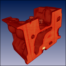
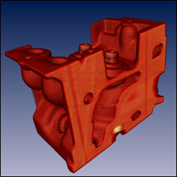
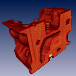
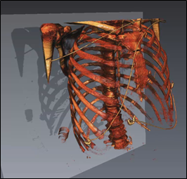
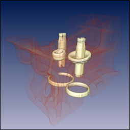
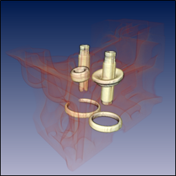
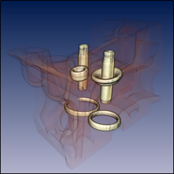
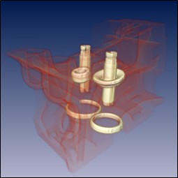
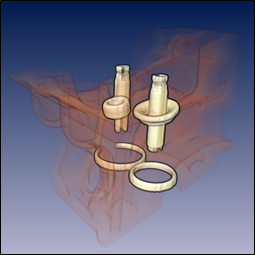
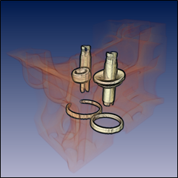
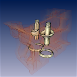
Volume rendering effects are enabled using fields in the SoVolumeRenderingQuality SoVolumeRenderingQuality SoVolumeRenderingQuality node. In this section we discuss the following effects:
Lighting is a key technique for “illuminating” the shapes of objects and the spatial relationship of objects in the scene. As much as possible, lighting of volumes is consistent with lighting of polygonal geometry in core Open Inventor. However there are some issues specific to volume rendering and some differences from lighting of VolumeViz slice primitives.
Unlike other Open Inventor geometry (including slice primitives), the appearance of volume rendering primitives is not automatically affected by lighting. Lighting must be explicitly enabled using the SoVolumeRenderingQuality SoVolumeRenderingQuality SoVolumeRenderingQuality node. Enabling volume lighting will reduce rendering performance. Unlike other Open Inventor geometry, if there is no light in the scene the voxels in the volume will still be rendered in their basic color defined by the transfer function and the SoMaterial SoMaterial SoMaterial node (if any). Volume lighting is not affected by the SoLightModel SoLightModel SoLightModel node.
Volume lighting supports directional, point and spot lights like other geometry. But unlike other Open Inventor geometry (including slice primitives), only one light is used to computing lighting for volume rendering. Volume rendering will use the first light traversed in the scene graph. This will normally be the viewer's "headlight", but does not have to be. The light direction (if applicable) affects volume rendering, but the light color and intensity are not considered for volume rendering.
Like other Open Inventor geometry, when lighting is enabled volume rendering primitives can cast and receive shadows. Shadows may be useful in some applications to give visual cues about the relationships (particularly depth ordering) of objects in the scene. To enable shadows, put the SoVolumeRender SoVolumeRender SoVolumeRender node under an SoShadowGroup SoShadowGroup SoShadowGroup node and set the shadow group’s method field to VARIANCE_SHADOW_MAP.
Lighting is enabled by adding an SoVolumeRenderingQuality SoVolumeRenderingQuality SoVolumeRenderingQuality node to the scene graph and setting its lighting field to true. Do NOT use the lighting field in the SoVolumeRender SoVolumeRender SoVolumeRender node (this enables a deprecated software lighting algorithm). When lighting is enabled, VolumeViz computes gradients and computes the lighting equation on the GPU during rendering.
Open Inventor uses the Phong lighting model (same as OpenGL) for geometry and for volume rendering. This means the appearance of the volume is affected by the SoMaterial SoMaterial SoMaterial node fields ambientColor, diffuseColor, specularColor, emissiveColor, shininess and transparency. The basic diffuseColor and opacity of a voxel is determined by the SoDataRange SoDataRange SoDataRange and SoTransferFunction SoTransferFunction SoTransferFunction nodes.
![[Note]](../../images/note.jpg) | |
Note: These values are multiplied with the material node settings, i.e voxelAlpha = materialAlpha * transferFunctionAlpha where materialAlpha = 1 - transparency. So materialAlpha is effectively a global setting for the entire volume. |
The effect of light on an object depends on the normal vector at each point on the surface. Classic polygonal and NURBS geometry defines true surfaces. Surface normal vectors can be computed from the geometry, for example by using cross product on each face then averaging the face normals at each vertex. Volume data may or may not contain surfaces. If it does we may be able to detect the surface indirectly as a significant transition from one material (voxel value) to another. Therefore we use the gradient of the voxel values as an approximation of a normal vector. For various algorithms we may be interested in the direction or the magnitude of the gradient vector or both. Illuminating transitions between different materials in the volume can be very effective for volumes containing sharp gradients such as bone to soft tissue in medical (CT) data or metal to air in materials data. There are many ways (with various tradeoffs) to compute the gradient at a voxel. VolumeViz provides several common algorithms through the gradientQuality field. It is also possible to skip or modify lighting according to the gradient magnitude.
Using the gradient vector as the surface normal for lighting can be problematic in some cases. The gradient vector will be approximately zero length in homogeneous regions where there is very little or no change in voxel values, making the normal vector undefined. And in practice, volume data sets contain noise which may cause small randomly oriented gradient vectors to be computed in relatively homogeneous regions. This can result in surfaces that should be relatively smooth appearing rough. VolumeViz provides several options to deal with this problem including the gradientThresold, surfaceScalarExponent and unnormalizedGradientExponent fields discussed in the following text.
|
|
|
|
|
|
|
|
|
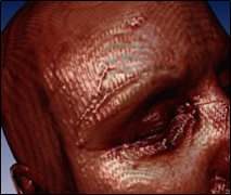
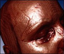
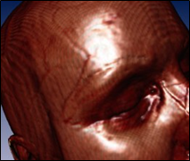
VolumeViz computes gradients "on the fly" for rendering. This increases the amount of GPU memory available for volume data because it is not necessary to store gradients in memory. The gradientQuality field (SoVolumeRenderingQuality SoVolumeRenderingQuality SoVolumeRenderingQuality ) selects the algorithm used to compute gradients. All of these methods are approximate. The difference is the tradeoff of computation time versus accuracy. The LOW setting uses the "forward difference" algorithm. This method is very fast but the gradients are not very accurate because only one neighboring voxel is considered. The MEDIUM setting uses the "central difference" algorithm. This is the default setting and a reasonable compromise between speed and quality. It considers two neighboring voxels. The HIGH setting uses a Sobel filter to compute the gradient. This is slower but much more accurate because it considers a 3x3 neighborhood around the voxel.
|
|
|
|
Noisy data may yield gradient vectors with small magnitudes and random directions that scatter light randomly rather than showing material changes in the volume. The gradientThreshold field (SoVolumeRenderingQuality SoVolumeRenderingQuality SoVolumeRenderingQuality ) provides a way to avoid this effect. If gradientTheshold is greater than zero, voxels having a gradient magnitude less than the specified threshold are not lighted. They are rendered using their basic color from the transfer function. The default is 0, meaning that all gradients are used in the lighting computation. A typical value is 0.1. The maximum useful value is 1.0, because gradient vectors are normalized. The visual effect is similar to the surfaceScalarExponent field. The difference is explained below.
|
|
|
Noisy data may yield gradient vectors with small magnitudes and random directions that scatter light randomly rather than showing material changes in the volume. The surfaceScalarExponent field (SoVolumeRenderingQuality SoVolumeRenderingQuality SoVolumeRenderingQuality ) provides a way to avoid this effect. If the surfaceScalarExponent is greater than or equal to 1, voxels with small gradients will be less lighted than voxels with large gradients. If the value is less than 1, the field is ignored. Values higher than 256 will apply lighting on almost all surfaces. For most datasets, values between 2 and 16 should be enough. A typical value is 8. The default is 0.
|
|
|
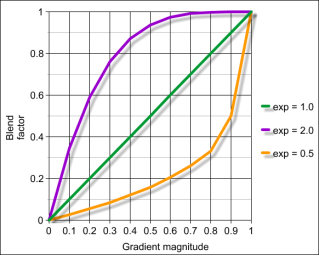
The final voxel color is a blend between the non-lighted voxel color (the basic color from the transfer function) and the lighted voxel color. The blending factor ranges from 0 (completely the non-lighted color) to 1 (completely the lighted color) and is computed from the gradient magnitude using an inverse "power function" where surfaceScalarExponent is the exponent value. Using a power function provides a lot of flexibility over the effect of this option. As shown below, if the exponent is 1, the blend factor is a linear function of the (normalized) gradient magnitude. For exponent values greater than 1, the blend factor reaches 1 (lighted color) much more quickly. For exponent values less than 1, the blend factor reaches 1 (lighted color) much more slowly. The visual effect of this field is similar to the gradientThreshold field. But if the effect of gradientThreshold was plotted like the graphs below, it would be a step function. The surfaceScalarExponent field provides a smooth transition from unlighted voxels to lighted voxels.
>Unnormalized gradient exponent:
When the unnormalizedGradientExponent field (SoVolumeRenderingQuality SoVolumeRenderingQuality SoVolumeRenderingQuality ) is greater than 0, the contribution of diffuse and specular lighting is reduced for voxels with small gradients. In other words ambient color will be the biggest contributor to the color of these voxels. The higher this value is, the more smaller gradients will contribute to lighting. Like surfaceScalarExponent, the reduction factor is computed from the gradient magnitude using an inverse power function where unnormalizedGradientExponent is the exponent value. Unlike surfaceScalarExponent, which affects all lighting factors, this field only affects the diffuse and specular values. Values higher than 256 will apply lighting on almost all surfaces. For most datasets, values between 2 and 16 should be enough. The default is 0.
This effect highlights the “edges” of structures in the volume by blending the voxel color with an edge color. Highlighting edges can be useful to visually separate structures inside the volume. For the edge coloring effect, edges are identified based on the gradient direction (normal vector). This effect is independent of lighting, but depends on the gradientQuality field (the section called “Lighting”) and related gradient computation options. Voxels whose normal vector is facing the camera are not modified. Voxels whose normal vector is more perpendicular to the view direction will tend towards the color specified in the edgeColor field. Edge coloring is most effective for voxels with relatively high opacity.
Edge coloring is enabled by setting the SoVolumeRenderingQuality SoVolumeRenderingQuality SoVolumeRenderingQuality field edgeColoring to true (default is false). The color used to highlight edges can be specified using the SoVolumeRenderingQuality SoVolumeRenderingQuality SoVolumeRenderingQuality field edgeColor (default is black). The intensity of the edge coloring effect can be specified using the SoVolumeRenderingQuality SoVolumeRenderingQuality SoVolumeRenderingQuality field edgeThreshold (default is 0.2). The minimum value is 0. There is no maximum, but in most cases a value between 0 and 1 is appropriate.
Edges can also be highlighted using boundary opacity (the section called “Boundary opacity”) and 2D edge detection (the section called “Edge detection (2D)”).
|
|
|
|
|
|
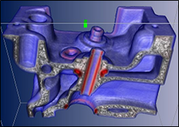
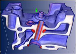
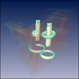
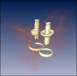
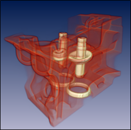
This effect highlights surfaces in the volume by automatically increasing each voxel's opacity based on the magnitude of its gradient vector. The gradient magnitude measures the change in voxel value compared to neighboring voxels. A larger gradient magnitude indicates a transition from one material to another. This effect is independent of lighting, but depends on the gradientQuality and gradientTheshold fields discussed in the lighting section (the section called “Lighting”), as well as related gradient computation options. Boundary opacity computes a value that is added to the voxel's current opacity (from the transfer function). So this effect is mainly useful for voxels with relatively low opacity. Even voxels with zero opacity (from the transfer function) can made visible using this effect. Boundary opacity is especially useful to highlight the shape of low(er) density material surrounding high(er) density material, for example soft tissues surrounding bone in medical data or different materials in non-destructive testing data.
|
|
|
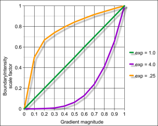
Boundary opacity is enabled by setting the SoVolumeRenderingQuality SoVolumeRenderingQuality SoVolumeRenderingQuality field boundaryOpacity to true (default is false). The SoVolumeRenderingQuality SoVolumeRenderingQuality SoVolumeRenderingQuality field boundaryOpacityIntensity (default 1.5) specifies the base value to be added to the voxel intensity. The actual value added to the voxel opacity is the base value multiplied by a scale factor computed from the gradient magnitude using a power function. If the scale factor is 0, no additional opacity is added. If the scale factor is 1, the full value of boundaryOpacityIntensity is added. The SoVolumeRenderingQuality SoVolumeRenderingQuality SoVolumeRenderingQuality field boundaryOpacityThreshold (default 1.5) specifies the exponent used in the power function to compute the scale factor. (Note that this value is not a "threshold" in the usual sense of the word.) Using a power function provides a lot of flexibility over the effect of this option. As shown below, if the exponent is 1, the scale factor is a linear function of the (normalized) gradient magnitude. For exponent values greater than 1, the scale factor reaches 1 much more slowly. For exponent values less than 1, the scale factor reaches 1 much more quickly (much more opacity is added).
If the SoVolumeRenderingQuality SoVolumeRenderingQuality SoVolumeRenderingQuality field gradientThreshold is greater than zero (default is 0), voxels with gradient magnitude less than this value are not affected by boundary opacity.
Edges can also be highlighted using edge coloring (the section called “Edge coloring”) and 2D edge detection (the section called “Edge detection (2D)”).
This effect highlights the "edges" of structures in the volume by darkening the voxel color. For the edge detection effect, edges are identified using a 2D image processing step based on change in luminance, depth and/or gradient. This effect depends on lighting (the section called “Lighting”) for the LUMINANCE method and depends on the gradientQuality field and related gradient computation options for the GRADIENT method. Edge detection is most effective for voxels with relatively high opacity.
Edge detection is enabled by setting the SoVolumeRenderingQuality SoVolumeRenderingQuality SoVolumeRenderingQuality field edgeDetect2D to true (default is false). The edge detection method can be specified using the SoVolumeRenderingQuality SoVolumeRenderingQuality SoVolumeRenderingQuality field edgeDetect2DMethod (default is LUMINANCE). The GRADIENT method is the most computationally expensive and the gradient changes may be too noisy to give interesting edges. The LUMINANCE (brightness) method has very little impact on rendering performance but can also detect edges that are really noise. The DEPTH method is in-between in performance impact, but the results are generally better. “Noise” edges can be reduced in all cases using the SoVolumeRenderingQuality SoVolumeRenderingQuality SoVolumeRenderingQuality fields edgeDetect2DInnerThreshold (default is 0.1) and edgeDetect2DOuterThreshold (default is 0.1).
Edges can also be highlighted using edge coloring (the section called “Edge coloring”) and boundary opacity (the section called “Boundary opacity”).
|
|
|
|
|
|
