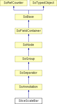
SliceScaleBar Class Reference
[Nodes]
 [PREVIEW] [Medical] Shape node to display a dynamic scale bar in window coordinates.
More...
#include <Medical/nodes/SliceScaleBar.h>

Public Types | |
| enum | Orientation { HORIZONTAL = 0, VERTICAL = 1 } |
| enum | Alignment { LEFT = 0, BOTTOM = 0, CENTER = 1, RIGHT = 2, TOP = 2 } |
Public Member Functions | |
| virtual SoType | getTypeId () const |
| SliceScaleBar () | |
Static Public Member Functions | |
| static SoType | getClassTypeId () |
| static void | initClass () |
| static void | exitClass () |
Public Attributes | |
| SoSFVec2f | position |
| SoSFFloat | length |
| SoSFInt32 | numTickIntervals |
| SoSFNode | trackedCamera |
| SoSFEnum | orientation |
| SoSFEnum | alignment |
| SoSFString | label |
Detailed Description
 [PREVIEW] [Medical] Shape node to display a dynamic scale bar in window coordinates.
This class displays a 2D scale bar. The position of the scale bar is specified in normalized screen coordinates (-1 to 1). By default, the length of the scale bar is a fixed distance in normalized screen coordinates. However if the trackedCamera field is set, then length is a distance in 3D world coordinates and the the size of the scale bar on screen is computed based on that distance. For example, if the application is viewing DICOM data measured in millimeters (mm), then setting length to 100 displays a scale bar that shows the distance 10 cm on screen. The scale bar size will change if the camera is zoomed in or out (camera height field changes).
The distance computation is based on "horizontal" or "vertical" relative to the camera, so the scale bar adjusts automatically if the camera is rotated to view a different volume axis, e.g. Coronal vs Axial.
This class is not intended to replace the MeshViz axis classes for general 2D data plotting. This class has only been tested with SoOrthoSlice and an SoOrthographicCamera (the usual case for medical image viewing).
FILE FORMAT/DEFAULT
- SliceScaleBar {
| position | 0 0 0 |
| length | 1 |
| numTickIntervals | 0 |
| trackedCamera | null |
| orientation | HORIZONTAL |
| alignment | CENTER |
| label | "" |
SEE ALSO
InventorMedical, DicomInfo, Gnomon, Magnifier, Ruler, SliceOrientationMarkers
Member Enumeration Documentation
Constructor & Destructor Documentation
| SliceScaleBar::SliceScaleBar | ( | ) |
Constructor.
Member Function Documentation
| static void SliceScaleBar::exitClass | ( | ) | [static] |
Finish using the class.
Reimplemented from SoAnnotation.
| static SoType SliceScaleBar::getClassTypeId | ( | ) | [static] |
Returns the type identifier for this class.
Reimplemented from SoAnnotation.
| virtual SoType SliceScaleBar::getTypeId | ( | ) | const [virtual] |
Returns the type identifier for this specific instance.
Reimplemented from SoAnnotation.
| static void SliceScaleBar::initClass | ( | ) | [static] |
Initialize the class.
Reimplemented from SoAnnotation.
Member Data Documentation
Scale bar alignment (default is CENTER).
Label (default is empty string).
Length in normalized screen coordinates (-1 to 1) if not tracking, else length in 3D world coordinates.
Default is 1.
For example, if the application is viewing DICOM data measured in millimeters (mm), then setting length to 100 displays a 10 cm scale bar on screen.
Number of tick intervals (default is 0).
If numTickIntervals is 0, no tick marks are drawn. For example, if the length is set to 100 mm, then set numTickIntervals to 10 to get a tick mark every 10 mm (1 cm).
Scale bar orientation (default is HORIZONTAL).
Position in normalized screen coordinates (-1 to 1).
Default is (0,0,0).
Tracked camera (default is null).
This should be the camera that is viewing the tracked scene. It will be used to determine the length of the axis in NDC based on the specified length in 3D world coordinates.
The documentation for this class was generated from the following file:
- Medical/nodes/SliceScaleBar.h