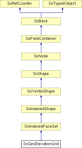
SoGeoElevationGrid Class Reference
[Geographic nodes]
 Specifies a uniform grid of elevation values within some spatial reference frame.
More...
#include <Inventor/geo/SoGeoElevationGrid.h>

Public Member Functions | |
| virtual SoType | getTypeId () const |
| SoGeoElevationGrid () | |
Static Public Member Functions | |
| static SoType | getClassTypeId () |
Public Attributes | |
| SoSFFloat | yScale |
| SoSFVec3f | geoGridOrigin |
| SoMFString | geoSystem |
| SoMFFloat | height |
| SoSFInt32 | xDimension |
| SoSFFloat | xSpacing |
| SoSFInt32 | zDimension |
| SoSFFloat | zSpacing |
Detailed Description
 Specifies a uniform grid of elevation values within some spatial reference frame.
The SoGeoElevationGrid allows to create terrain models for local or large areas (automatically introduces correct degree of earth curvature).
The SoGeoElevationGrid node specifies a uniform grid of elevation values within some spatial reference frame. These are then transparently transformed into a geocentric, curved-earth representation. For example, this would allow a geographer to create a height field where all coordinates are specified in terms of latitude, longitude, and elevation. The geoSystem field is used to define the spatial reference frame and is described in 25.2.3 Specifying a spatial reference frame. The geoGridOrigin field specifies the geographic coordinate for the south-west corner (bottom-left) of the dataset. This value should be specified as described in 25.2.4 Specifying geospatial coordinates. The height array contains xDimension zDimension floating point values that represent elevation above the ellipsoid or the geoid, as appropriate. These values are given in row-major order from west to east, south to north. When the geoSystem is "GD", xSpacing refers to the number of degrees of longitude between adjacent height values and zSpacing refers to the number of degrees of latitude between vertical height values. When the geoSystem is "UTM", xSpacing refers to the number of eastings (meters) between adjacent height values and zSpacing refers to the number of northings (meters) between vertical height values. EXAMPLE If xDimension = n and the grid spans d units horizontally, the xSpacing value should be set to: d / (n-1). The yScale value can be used to produce a vertical exaggeration of the data when it is displayed. By default, this value is 1.0 (no exaggeration). If this value is set greater than 1.0, all heights will appear larger than actual.
FILE FORMAT/DEFAULT
- GeoElevationGrid {
| yScale | 1.0 |
| geoGridOrigin | 0 0 0 |
| geoSystem | ["GD","WE"] |
| height | [] |
| xDimension | 0 |
| xSpacing | 1.0 |
| zDimension | 0 |
| zSpacing | 1.0 |
ACTION BEHAVIOR
- SoGLRenderAction
- GC: Earth-fixed Geocentric with respect to the WGS84 ellipsoid.
- GD: Geodetic spatial reference frame.
An optional second string may be used to specify the ellipsoid used. If no ellipsoid is specified, then "WE" is assumed (the WGS84 ellipsoid). - UTM: Universal Transverse Mercator
One further required argument must be supplied for UTM in order to specify the zone number (1..60). This is given in the form "Zn", where n is the zone number. An optional argument of "S" may be supplied in order to specify that the coordinates are in the southern hemisphere (otherwise, northern hemisphere will be assumed). - Inventor/geo/SoGeoElevationGrid.h
Constructor & Destructor Documentation
| SoGeoElevationGrid::SoGeoElevationGrid | ( | ) |
Constructor.
Member Function Documentation
| static SoType SoGeoElevationGrid::getClassTypeId | ( | ) | [static] |
Returns the type identifier for this class.
Reimplemented from SoIndexedFaceSet.
| virtual SoType SoGeoElevationGrid::getTypeId | ( | ) | const [virtual] |
Returns the type identifier for this specific instance.
Reimplemented from SoIndexedFaceSet.
Member Data Documentation
Specifies the geographic coordinate for the south-west corner (bottom-left) of the dataset.
Defines the spatial reference frame.
Valid values are:
The height array contains xDimension * zDimension floating point values that represent elevation above the ellipsoid or the geoid, as appropriate.
These values are given in row-major order from west to east, south to north.
Number of X values in the grid.
Spacing between X values.
When the geoSystem is "GD", xSpacing refers to the number of degrees of longitude between adjacent height values. When the geoSystem is "UTM", xSpacing refers to the number of eastings (meters) between adjacent height values.
The yScale value can be used to produce a vertical exaggeration of the data when it is displayed.
By default, this value is 1.0 (no exaggeration). If this value is set greater than 1.0, all heights will appear larger than actual.
Number of Z values in the grid.
Spacing between Z values.
When the geoSystem is "GD", zSpacing refers to the number of degrees of latitude between vertical height values. When the geoSystem is "UTM", zSpacing refers to the number of northings (meters) between vertical height values.
The documentation for this class was generated from the following file: