SoGeodesicPropagationProcessing2d Class Reference
[Distance Maps]
 SoGeodesicPropagationProcessing2d engine
More...
SoGeodesicPropagationProcessing2d engine
More...
#include <ImageViz/Engines/MathematicalMorphology/DistanceMaps/SoGeodesicPropagationProcessing2d.h>
Public Member Functions | |
| SoGeodesicPropagationProcessing2d () | |
Public Attributes | |
| SoSFImageDataAdapter | inBinaryImage |
| SoImageVizEngineOutput < SoSFImageDataAdapter, SoImageDataAdapter * > | outImage |
Detailed Description
SoGeodesicPropagationProcessing2d engine
For an introduction to geodesy, see section Geodesy Principle.
The result of the SoGeodesicPropagationProcessing2d Command, applied to a binary image without holes, is a grey level image where each pixel has a grey level value equal to  . The following image contains the result of a geodesic propagation on an image to differentiate the various grey level values appearing as stripes or rings. For the largest particle,
  has a minimum of 36 and then values spread until 70 at the extremities. It means that the shortest distance is 36 and the length of the particle can be considered as equal to 70. For particles close to a disk, the geodesic center is located at the center of the particle, and points with the same grey level value are concentric rings.
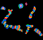
Geodesic propagation
The geodesic function has a minimum for each particle which is either a point or a region, named the geodesic center of the particle. The value of this minimum is named the geodesic radius of the particle, as a circle drawn from any of the geodesic center points with such a radius will hit the extremities of the particle.
The maximum is reached at points usually located at the extremities of the particles named geodesic extremities. The value of this maximum is named the geodesic diameter and is seldom equal to 2 times the geodesic radius. In the case of a disk, the center is the geodesic center and the diameter is the geodesic diameter.
FILE FORMAT/DEFAULT
- GeodesicPropagationProcessing2d {
| inBinaryImage | NULL |
Library references: propagation
Constructor & Destructor Documentation
| SoGeodesicPropagationProcessing2d::SoGeodesicPropagationProcessing2d | ( | ) |
Constructor.
Member Data Documentation
The input binary image.
Default value is NULL. Supported types include: binary color image.
| SoImageVizEngineOutput<SoSFImageDataAdapter,SoImageDataAdapter*> SoGeodesicPropagationProcessing2d::outImage |
The output image.
Default value is NULL. Supported types include: grayscale binary label color image.
The documentation for this class was generated from the following file:
- ImageViz/Engines/MathematicalMorphology/DistanceMaps/SoGeodesicPropagationProcessing2d.h