SoInfluenceZonesProcessing Class Reference
[Hit-Or-Miss And Skeleton]
 SoInfluenceZonesProcessing engine
More...
SoInfluenceZonesProcessing engine
More...
#include <ImageViz/Engines/MathematicalMorphology/HitOrMissAndSkeleton/SoInfluenceZonesProcessing.h>
Public Member Functions | |
| SoInfluenceZonesProcessing () | |
Public Attributes | |
| SoSFEnum | computeMode |
| SoSFEnum | neighborhood3d |
| SoSFImageDataAdapter | inObjectImage |
| SoImageVizEngineOutput < SoSFImageDataAdapter, SoImageDataAdapter * > | outBinaryImage |
Detailed Description
SoInfluenceZonesProcessing engine
The SoInfluenceZonesProcessing engine computes the skeleton by Influence Zone (SKIZ).
For an introduction, see section :
Skeletonization is used to produce a simplified representation of the objects in an image, while preserving their geometrical structure. The representation may then be used to calculate length, direction, etc. or to detect special topological structures such as end or triple points (number of crossings). Skeletonization is a transformation based on the thinning of connected components until a line is achieved.
This engine produces a pruned skeleton of the background. The influence zone of a particle X is the set of points closer to X than to any other particle Y. The skeleton by influence zones is the boundary splitting the different influence zones, and it separates the image into zones surrounding each object.
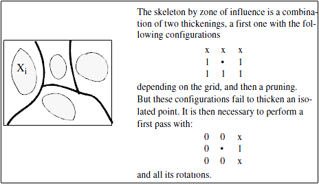
Skeleton by influence zones
This engine searches the skeleton of a binary or labelled image by influence zones. If the input is a binary image, it is first labelled, then the influence zones are determined by successive conditional dilations. The process stops as soon as all the zones are hitting each other.
FILE FORMAT/DEFAULT
- InfluenceZonesProcessing {
| computeMode | MODE_AUTO |
| neighborhood3d | CONNECTIVITY_26 |
| inObjectImage | NULL |
Library references: skiz
Constructor & Destructor Documentation
| SoInfluenceZonesProcessing::SoInfluenceZonesProcessing | ( | ) |
Constructor.
Member Data Documentation
Select the compute Mode (2D or 3D or AUTO) Use enum ComputeMode.
Default is MODE_AUTO
The input binary or label image.
Default value is NULL. Supported types include: binary label color image.
In 3D configuration (see computeMode), the neighborhood connectivity defines the connectivity considered for processing adjacent voxels.
Use enum Neighborhood3d. Default is CONNECTIVITY_26.
| SoImageVizEngineOutput<SoSFImageDataAdapter,SoImageDataAdapter*> SoInfluenceZonesProcessing::outBinaryImage |
The output binary image.
Default value is NULL. Supported types include: binary image.
The documentation for this class was generated from the following file:
- ImageViz/Engines/MathematicalMorphology/HitOrMissAndSkeleton/SoInfluenceZonesProcessing.h