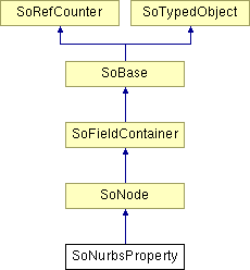
SoNurbsProperty Class Reference
[Properties]
Node that defines additional properties for rendering a NURBS surface. More...
#include <Inventor/nodes/SoNurbsProperty.h>

Public Types | |
| enum | DrawStyle { NORMAL = 0x01, BOUNDARIES_AND_TRIM_CURVES = 0x02, CENTRAL_ISO_PARAM_CURVES = 0x04 } |
| enum | TessellationType { CONSTANT, ADAPTIVE } |
Public Member Functions | |
| virtual SoType | getTypeId () const |
| SoNurbsProperty () | |
Static Public Member Functions | |
| static SoType | getClassTypeId () |
Public Attributes | |
| SoSFBitMask | drawStyle |
| SoSFInt32 | numSamplePoints |
| SoSFColor | color |
| SoSFUShort | isoParamCurvesPattern |
| SoSFEnum | tessellationType |
| SoSFFloat | tessellationDistance |
| SoSFFloat | tessellationAngle |
Detailed Description
Node that defines additional properties for rendering a NURBS surface.
This node defines an additional set of properties used by SoNurbsSurface when rendering NURBS surfaces.
For a large NURBS surface, it is sometimes more effective to display two central isoparametric curves rather than facet boundaries (as in wireframe mode) because the latter may provide an overly complicated view of the surface.
This node allows you to specify the NURBS draw style; the color of the trim curves, boundaries and isoparametric curves; the line pattern of the isoparametric curves; the number of sample points between trim curves control points; the type of tessellation; angle and distance for adaptive tessellation.
The NURBS draw style is a bitmask specifying which combination of the following representations to use for displaying the NURBS: normal display, trim curves and boundaries, and/or central isoparametric curves.
Turning off the normal NURBS surface display, and turning on the display of trim curves, boundaries and isoparametric curves can dramatically speed up rendering of large models.
When in ADAPTIVE tessellation mode, regions with a low curvature will be less tessellated than regions with a high curvature.
FILE FORMAT/DEFAULT
- NurbsProperty {
| drawStyle | NORMAL |
| numSamplePoints | -1 |
| color | 1 1 1 |
| isoParamCurvesPattern | 0xFFFF |
| tessellationType | CONSTANT |
| tessellationDistance | 0.01 |
| tessellationAngle | 0.35 |
ACTION BEHAVIOR
- Sets: SoNurbsPropertyElement
SEE ALSO
- See related examples:
Member Enumeration Documentation
Tesselation type.
- Enumerator:
CONSTANT The tessellation step size is constant and the same for both the U and V axes.
The tessellation step size depends on SoComplexity::value.
ADAPTIVE The tessellation depends on the curvature of the geometry.
Regions with a low curvature will be less tessellated than regions with a high curvature.
Constructor & Destructor Documentation
| SoNurbsProperty::SoNurbsProperty | ( | ) |
Constructor.
Member Function Documentation
| static SoType SoNurbsProperty::getClassTypeId | ( | ) | [static] |
Returns the type identifier for this class.
Reimplemented from SoNode.
| virtual SoType SoNurbsProperty::getTypeId | ( | ) | const [virtual] |
Returns the type identifier for this specific instance.
Reimplemented from SoNode.
Member Data Documentation
Contains the color used to render trim curves and isoparametric curves.
Indicates which part of the NURBS surface to render.
Use enum DrawStyle. Default is NORMAL.
Sets a specific line pattern for isoparametric curves.
numSamplePoints is used during trim curve tessellation.
It specifies the exact number of points to generate between two trim curve control points. If set to -1 (the default), the number of points generated is computed from the SoComplexity node. Setting this field to a small value (less than 3) can reduce the number of triangles generated by the tessellation and thus increase the drawing performance of trimmed NURBS surfaces.
Used when tessellationType is set to ADAPTIVE.
Specifies the maximum angle (in radians) between the normals of two adjacent tessellated faces. Decreasing this value adds more tessellation points on flat parts of the surface. Default value is 0.35
NOTE: field available since Open Inventor 6.0Used when tessellationType is set to ADAPTIVE.
The maximum tessellation step size (curvilinear distance) is this fraction of the diagonal of the bounding box of the surface or the group of surfaces (SoNurbsGroup). Increasing this value make the tessellation more dependent on tessellationAngle. Default value is 0.01. That is, the distance must not be more than 1% of the diagonal of the bounding box.
NOTE: field available since Open Inventor 6.0Specifies the tessellation type.
* Use enum TessellationType. Default is CONSTANT.
NOTE: field available since Open Inventor 6.0The documentation for this class was generated from the following file:
- Inventor/nodes/SoNurbsProperty.h