SoViewingCube Class Reference
[Nodes]
Interactive cubic shape to control the orientation of a camera. More...
#include <Inventor/ViewerComponents/nodes/SoViewingCube.h>
Public Types | |
| enum | PositionInViewport { TOP_RIGHT, TOP_LEFT, BOTTOM_RIGHT, BOTTOM_LEFT } |
| enum | EdgeStyle { FLAT, ROUND, CORNER } |
Public Member Functions | |
| virtual SoType | getTypeId () const |
| SoViewingCube () | |
| virtual SbBool | affectsState () const |
Static Public Member Functions | |
| static SoType | getClassTypeId () |
Public Attributes | |
| SoSFNode | sceneCamera |
| SoSFVec2f | size |
| SoSFEnum | position |
| SoSFEnum | edgeStyle |
| SoSFColor | selectionColor |
| SoSFColor | faceColor |
| SoSFColor | edgeColor |
| SoSFColor | cornerColor |
| SoSFFilePathString | facePosX |
| SoSFFilePathString | faceNegX |
| SoSFFilePathString | facePosY |
| SoSFFilePathString | faceNegY |
| SoSFFilePathString | facePosZ |
| SoSFFilePathString | faceNegZ |
| SoSFFloat | edgeSize |
| SoSFFloat | animationDuration |
| SoSFEnum | upAxis |
| SoSFFloat | opacityMin |
| SoSFFloat | opacityMax |
| SoSFNode | compass |
Detailed Description
Interactive cubic shape to control the orientation of a camera.
 [PREVIEW]
The viewing cube is an interactive shape that indicates the current orientation of a camera (like a "compass" or "gnomon") and also responds to user actions by re-orienting the associated camera to one of the predefined orientations. These orientations are defined so that the camera will be in front of a selected part of the bounding cube of the scene.
Interactions
When the mouse cursor is over the viewing cube, the part (face, edge, or corner) that is under the cursor is highlighted with the selectionColor. Then if the left mouse button (button 1) is clicked (pressed and released), the selected part of the viewing cube is used to define the new orientation.
The viewing cube can be used as a replacement for the X/Y/Z camera orientation buttons implemented in many graphical user interfaces. It provides even more possibilities thanks to the pickable edges and corners of the viewing cube which offer 26 different viewing positions. However, if the edgeSize is set to 0, the edges and corners are not pickable. In this case the user can only select six different positions.
The camera controlled by the viewing cube is defined by the field sceneCamera. This is normally the same camera that the 3D viewer is controlling. In this case both the viewer and the viewing cube control the camera and the viewing cube orientation is synchronized with the sceneCamera.
In principle, as SoViewingCube is a standard class derived from SoNode, it can be inserted in any scene graph and used with a classical viewer or SceneExaminer class. In that case the viewing cube will correctly indicate the camera orientation, but it will not be convenient for the user to use the viewing cube's interaction features. These viewers are always in either viewing mode (mouse events control the camera) or in selection mode (mouse events are sent to the scene graph). In viewing mode, the viewing cube will not respond to mouse clicks, but in selection mode the viewer will not respond to mouse clicks.
Therefore we recommend to use the SceneOrbiter class as the viewer when using a viewing cube. SceneOrbiter is a "mode less" viewer. A mouse click without moving the mouse is interpreted as a selection (for example triggering the viewing cube behavior), but a mouse click and "drag" is interpreted as controlling the camera. For convenience, the SceneOrbiter automatically adds a viewing cube to the scene graph.
The viewing cube is rendered in a corner of the render area. Its size and position in the render area are defined by the size and position fields.
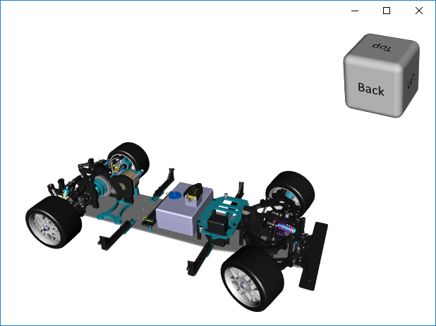
|
| viewing cube at the top right corner of a render area |
Rendering customization
When the mouse cursor is moved on top of the viewing cube, the part that is under the cursor is highlighted using the color defined by the field selectionColor. The colors of the cube can also be personalized with 3 fields: faceColor, edgeColor and cornerColor.
Cubic shape customization
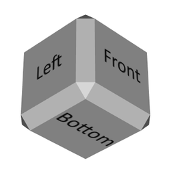
The shape of the viewing cube can be customized by several fields. The shape of the edges and corners is defined by the field edgeStyle. The edges can form a sharp corner, be rounded or be flat (beveled). The size of the edges and corners relative to the cube face is defined by the field edgeSize.
|
| edgeStyle=ROUND and edgeSize=0.1 |
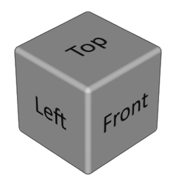
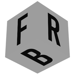
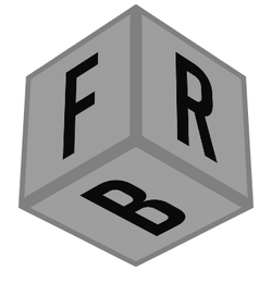
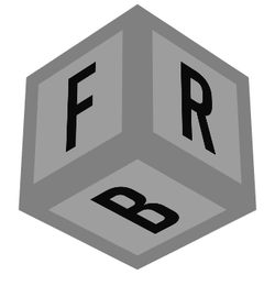
Each flat face of the viewing cube can also be customized. By default the text Top/Bottom/Front/Back/Left/Right appears on the center of each face according to its orientation. The six fields facePosX ... faceNegZ allow the application to replace the default appearance of each face with an image. Note that these images should have a transparent background so the highlight color is visible when the cursor is over the face.
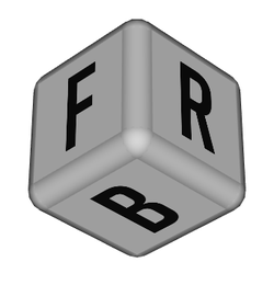
|
| viewing cube custom faces with F/R/B textures |
Opacity
The viewing cube's opacity may vary depending on the distance between it and the cursor.
- if the cursor is far from the center of the cube, the opacityMin is applied.
- if the cursor is very close or over the cube, the opacityMax is applied.
- otherwise the opacity varies in the range [opacityMin, opacityMax]
When the cursor moves in an area close to the cube but not over the cube and if the opacityMin and opacityMax differ, a rendering of the scene occurs each time the mouse is moved in this area, which can lead to slowing down of the application.
By default, opacityMin and opacityMax are set to 1, which means the cube is always opaque.
Limitations:
- Some visual artifact on semi transparent ViewingCube when you use NO_SORT transparency type.
- The opacity of the ViewingCube is only updated on a mouse move event without button pressed. Therefore the opacity won't change if you move the mouse without pressing a button.
Compass The compass is not impacted by the varying opacity, thus independently from the fields opacityMin and opacityMax
Animation
To provide a better user experience, picking a part of the viewing cube does not immediately change the camera orientation. A smooth animation is done between the current camera orientation and the new orientation. The duration of the animation is defined by the animationDuration field.
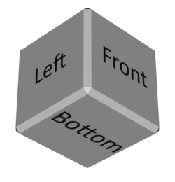
Note that the animation of the camera is done in such a way that the default text of each face Top/Bottom/Front/Back/Left/Right are always legible.
FILE FORMAT/DEFAULT
- ViewingCube {
| sceneCamera | NULL |
| size | (150.0, 150.0) |
| position | TOP_RIGHT |
| edgeStyle | ROUND |
| edgeSize | 0.4 |
| selectionColor | cyan |
| faceColor | 0.8 0.8 0.8 |
| edgeColor | 0.8 0.8 0.8 |
| cornerColor | 0.8 0.8 0.8 |
| animationDuration | 0.8 |
| upAxis | "Y" |
| facePosX | "" |
| faceNegX | "" |
| facePosY | "" |
| faceNegY | "" |
| facePosZ | "" |
| faceNegZ | "" |
| opacityMin | 1 |
| opacityMax | 1 |
| compass | NULL |
SEE ALSO
Member Enumeration Documentation
Possible positions of the viewing cube in the scene camera viewport.
Constructor & Destructor Documentation
| SoViewingCube::SoViewingCube | ( | ) |
Member Function Documentation
| virtual SbBool SoViewingCube::affectsState | ( | ) | const [virtual] |
| static SoType SoViewingCube::getClassTypeId | ( | ) | [static] |
Returns the type identifier for this class.
Reimplemented from SoNode.
| virtual SoType SoViewingCube::getTypeId | ( | ) | const [virtual] |
Returns the type identifier for this specific instance.
Reimplemented from SoNode.
Member Data Documentation
Duration of camera movement to reach the desired position.
Any negative value of this field is equivalent to 0 (no animation). Default is 0.8 seconds.
Defines an additional and optional scene graph to visualize a compass encapsulated in the viewing cube.
This scene graph will have to be centered on (0, 0, 0) to be aligned with the center of the viewing cube. According to its size, the compass will be visible or not when the viewing cube is opaque.
By default this field is NULL, so no compass is displayed. Some examples of simple compasses are provided in the folder $OIVHOME/examples/data/Inventor/ViewingCube/Compass
Color used to render the corners of the cube.
Default is gray (0.8,0.8,0.8).
Color used to render the edges of the cube.
Default is gray (0.8,0.8,0.8).
Size of the edges, relative to the size of the faces.
The size of the corners are also adjusted according to this value. When the edgeSize is 0, neither edges nor corners of the viewing cube can be highlighted or selected. Thus the viewing cube allows to select only 6 predefined positions of the camera.
This field's value is clamped in a range [0-1]. edgeSize = 1 corresponds to 25% of the face's size. Default is 0.4.
Depending on the edgeStyle value, the edgeSize defines either a radius (for ROUND style) or a width.
|
| Above is a viewing cube with edgeSize = 0 |
Below are images of a viewing cube with different edgeSize=0.1 on the left column and edgeSize=0.25 on the right column.
| 
|
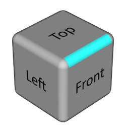
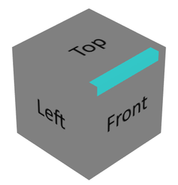
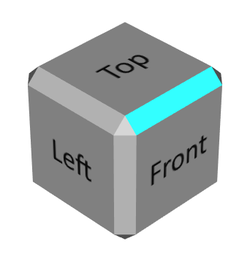
| edgeStyle = CORNER | |
|
|
|
| edgeStyle = ROUND | |
| 
|
| edgeStyle = FLAT |
Color used to render the faces of the cube.
Default is gray (0.8,0.8,0.8).
Texture to customize the face's appearance which has a "Left" label by default.
See facePosX for detail.
Texture to customize the face's appearance which has a "Bottom" label by default.
See facePosX for detail.
Texture to customize the face's appearance which has a "Back" label by default.
See facePosX for detail.
Texture to customize the face's appearance which has a "Right" label by default.
This field defines the name of the file which contains this texture.
The standard image file formats are supported. See SoRasterImageRW for the list. The image format must handle an alpha channel in order to allow the selected face to be highlighted with the selectionColor.
Texture to customize the face's appearance which has a "Top" label by default.
See facePosX for detail.
Texture to customize the face's appearance which has a "Front" label by default.
See facePosX for detail.
Defines the viewing cube opacity when the cursor is close to it or over it.
The value range is [0, 1].
Default is 1.
Defines the viewing cube opacity when the cursor is far from it.
The value range is [0, 1].
Default is 1.
Position of the viewing cube in the scene camera viewport.
Use enum PositionInViewport.
Default is TOP_RIGHT.
Camera which is synchronized with this viewing cube.
When using a viewing cube with a SceneOrbiter, the method SceneOrbiter::enableViewingCube(true) automatically sets the field sceneCamera.
However, to use a viewing cube with a SceneExaminer, the following code sample gives an example to set the field sceneCamera.
     qtViewerExaminer = new ViewerExaminer(NULL);
     SceneExaminer* sceneExaminer = qtViewerExaminer->getRenderArea()->getSceneInteractor();
     SoViewingCube* viewingCube = new SoViewingCube;
     viewingCube->sceneCamera = sceneExaminer->getCamera();
     sceneExaminer->addChild(viewingCube);
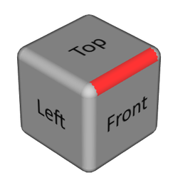
Color used to highlight the part of the viewing cube that is under the cursor.
Default is cyan (0,1,1).
The following image shows the highlighted edge behind the cursor when selectionColor = (1,0,0)
|
Size of the viewport, in pixels, in which the viewing cube is drawn.
Default is 150 pixels width, 150 pixels height.
Up axis of the scene.
Setting the up axis allows the adjustment of the viewing cube rotations. Thus, this axis remains vertical at all times relative to the viewport, it is always parallel to the vertical border of the viewport. The chosen axis defines the initial position and orientation of the camera (front-top-right corner). Use enum openinventor::inventor::Axis::Type. Default is Y.
The documentation for this class was generated from the following file:
- Inventor/ViewerComponents/nodes/SoViewingCube.h