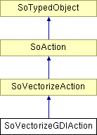
SoVectorizeGDIAction Class Reference
[HardCopy]
 Vectorize a scene graph to MS-Windows GDI formats.
More...
#include <HardCopy/SoVectorizeGDIAction.h>

Public Member Functions | |
| virtual SoType | getTypeId () const |
| SoVectorizeGDIAction () | |
| virtual | ~SoVectorizeGDIAction () |
| SoGDIVectorOutput * | getGDIVectorOutput () const |
| SbBool | hasPrinter () |
Static Public Member Functions | |
| static SoType | getClassTypeId () |
Detailed Description
 Vectorize a scene graph to MS-Windows GDI formats.
[Windows only] This class is not implemented on UNIX systems.
This class is used for vectorizing scene graphs to GDI format outputs. It contains an SoGDIVectorOutput instance which writes by default to the standard output (printer). Methods on the SoGDIVectorOutput can be called to specify the output type and its attributes (such as the EMF file name).
NOTE: If margin values are not valid for the targeted printer driver, it will be automatically reset to a correct one by the driver without prompting the user that the resulting output may not be exactly what he expected.
Printer Control:
By default this class controls the printer (making the StartDoc, StartPage, etc Windows system calls) and defines the logical to device coordinate system mapping. In some cases the application, or application framework (e.g. MFC) may wish to control the printer directly. This is possible by setting the preference variable OIV_HCGDI_APPCONTROL to a non-zero value, using either a config file or the SoPreferences class. When this variable is non-zero, the application is responsible for calling StartDoc, StartPage, EndPage and EndDoc to manage the printer. There are two modes, depending on the value of OIV_HCGDI_APPCONTROL:
- 1 : This is the most flexible mode. The application is responsible for setting the map mode, logical to device mapping, etc. (in addition to managing the printer). This mode is normally used in MFC applications.
- 2 : This is the most convenient mode if you only need to manage the printer. SoVectorizeGDIAction will set up the mapping as usual. This mode is only available in Open Inventor 7.2 and higher.
NOTE: When OIV_HCGDI_APPCONTROL is set, the methods that take parameters in physical units (e.g. millimeters) actually expect the values in current device units. For example, in this mode most applications call the GDI method SetMapMode() with HI_METRIC, meaning that device units are now .01 millimeter (provides better resolution for detailed drawings). As a result methods like setDrawingDimensions() and setNominalWidth must now be called with HI_METRIC units. For 1 mm, pass the value 100.
Polygon edge width:
GDI uses a "brush" to draw the interior of a polygon and a "pen" to draw the edges of the polygon. By default the action uses a minimum width line for the polygon edges, but it is possible to specify the edge width by setting the environment variable OIV_HCGDI_EDGE_WIDTH (see SoPreferences). Zero means minimum width. Values > 0 are a scale factor applied to the "nominalWidth" (see SoVectorizeAction::setNominalWidth) similar to the line width set with SoDrawStyle::lineWidth. This value is fetched in the constructor so it must be set before creating an SoVectorizeGDIAction.
Limitations:
- End line style TRIANGULAR is not supported end line style ROUND is assumed instead.
- Join line style NONE, MITERED_BEVELED, and TRIANGULAR are not supported; join line styles BEVELED, MITERED, and ROUNDED are assumed instead.
- End and Join line styles are only supported for solid lines.
- User's DC must be of HDC type.
- Vertical text orientation may not be kept when editing .emf files in third parties applications, for instance MS Word.
- A big value for the line width (defined with an SoDrawStyle) may result in previewing or printing solid lines though they remain patterned. It depends on how big gaps are in the pattern.
- See additional limitations in SoVectorizeAction.
Constructor & Destructor Documentation
| SoVectorizeGDIAction::SoVectorizeGDIAction | ( | ) |
Constructor.
| virtual SoVectorizeGDIAction::~SoVectorizeGDIAction | ( | ) | [virtual] |
Destructor.
Member Function Documentation
| static SoType SoVectorizeGDIAction::getClassTypeId | ( | ) | [static] |
Returns the type identifier for this class.
Reimplemented from SoVectorizeAction.
| SoGDIVectorOutput* SoVectorizeGDIAction::getGDIVectorOutput | ( | ) | const |
Returns the SoGDIVectorOutput instance in action.
| virtual SoType SoVectorizeGDIAction::getTypeId | ( | ) | const [virtual] |
Returns the type identifier for this specific instance.
Reimplemented from SoVectorizeAction.
| SbBool SoVectorizeGDIAction::hasPrinter | ( | ) | [inline] |
Returns TRUE if the printer is set.
Initial value is FALSE.
The documentation for this class was generated from the following file:
- HardCopy/SoVectorizeGDIAction.h