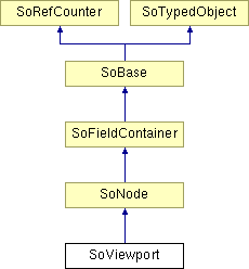
SoViewport Class Reference
[Properties]
 Viewport parameters node.
More...
#include <Inventor/nodes/SoViewport.h>

Public Member Functions | |
| virtual SoType | getTypeId () const |
| SoViewport () | |
Static Public Member Functions | |
| static SoType | getClassTypeId () |
Public Attributes | |
| SoSFVec2f | origin |
| SoSFVec2f | size |
Detailed Description
 Viewport parameters node.
This node specifies the viewport used for rendering.
The view volume specified by the current camera will be mapped into this region of the render target (e.g. the viewer window). By default Open Inventor manages the viewport to be the entire render target, even if the window (for example) is resized. So this node is useful for rendering objects in a specific part of the window, for example screen locked annotation graphics like legends and a "compass".
Remember that the camera node's viewportMapping field is set to ADJUST_CAMERA by default. In this mode the camera automatically adjusts its view volume to have the same aspect ratio as the viewport (widening for example) to avoid distorting shapes in the scene. But note that the camera will compare the aspect ratio of its view volume to the aspect ratio of the viewport that is in effect when the camera node is traversed. So it's generally better to create a camera for each viewport and make sure the camera node is traversed after the viewport node. If using multiple viewports with the same camera, generally the viewports should all have the aspect ratio.
Tip: You can use the SoDepthBuffer node to clear the depth buffer in the viewport region to ensure annotation graphics render correctly. However, in general, you should put an SoViewportClipping node before this node to limit the effect of the depth buffer clear to the desired viewport.
If you want to place multiple "views" inside the same window, consider the PoView and PoSceneView nodes. Views allow the application to specify multiple cameras, each with its own separate viewport Views can be used, for example, to subdivide the window into multiple independent views of a 3D scene or to create an inset "bird's eye" view inside the window, without the overhead of creating separate windows. The advantage of using the view nodes over SoViewport is that when mouse event locations are mapped back into 3D space, Open Inventor automatically uses the view volume of the camera associated with the view node whose viewport currently contains the mouse cursor.
NOTE: node available since Open Inventor 8.6FILE FORMAT/DEFAULT
- Viewport {
| origin | (0,0) |
| size | (0,0) |
ACTION BEHAVIOR
SEE ALSO
SbViewportRegion, SoViewportClipping, SoDepthBuffer, PoView, PoSceneView
- See related examples:
Constructor & Destructor Documentation
| SoViewport::SoViewport | ( | ) |
Constructor.
Member Function Documentation
| static SoType SoViewport::getClassTypeId | ( | ) | [static] |
Returns the type identifier for this class.
Reimplemented from SoNode.
| virtual SoType SoViewport::getTypeId | ( | ) | const [virtual] |
Returns the type identifier for this specific instance.
Reimplemented from SoNode.
Member Data Documentation
Specifies the position of the viewport in pixels.
(Although this is a float field, the values really are pixels, not normalized units.) Default is 0,0.
Specifies the size of the viewport in pixels.
(Although this is a float field, the values really are pixels, not normalized units.) Default is 0,0.
The documentation for this class was generated from the following file:
- Inventor/nodes/SoViewport.h