|
Open Inventor Release 2024.2.0
|
|

| |
|
Open Inventor Release 2024.2.0
|
|
|
| |
Setting the camera in stereo mode is the first step. The next step is to set the display in stereo mode. Open Inventor provides two types of stereo display: software and hardware. Hardware stereo relies on the OpenGL implementation and the graphics board, whereas software stereo relies on techniques independent of the graphics board.
The stereo modes for the display are set via the viewers. They automatically set the camera to the correct stereo mode. Therefore, in most situations, you can forget most of what you learned in Left and Right Eye Projections.
Whereas stereo mode for the camera means setting the projection matrix for each eye so that the scene will be rendered as if it were seen by each eye, the stereo modes for the display adapt each rendered view to a specific type of stereo technique. The supported stereo techniques are:
Each type of stereo is implemented by a separate class. The viewers are the basis for use of stereo display modes. Setting the stereo rendering mode for a viewer means passing an object of a particular stereo class to the viewer. All classes of stereo rendering are subclasses of the SoBaseStereo class.

"Important"
This is the only stereo mode supported in older versions (e.g., before Open Inventor 2.6) of Open Inventor. It is dependent on the OpenGL driver on the system as well as the graphics board. If an appropriate pixel format can be found for the current screen resolution, stereo is activated and works through the usual FRONT_LEFT / BACK_LEFT and FRONT_RIGHT / BACK_RIGHT OpenGL buffers. This mode has the advantage of being hardware accelerated and has almost no overhead between/after rendering.
Essentially all stereo modes reduce overall frame rate because of the need
to render each frame twice (left and right). It is implemented by the SoRawStereo class.
This type of stereo is important for light polarizing systems. Every other scanline on the screen is used for the left eye; the alternate scanlines are used for the right eye. This type of stereo is implemented by SoInterlacedStereo and actually has four modes. Two of them interleave horizontal lines, and two of them interleave vertical lines. In each category, one mode uses a fast algorithm and the other mode sacrifices speed for quality.
This type of stereo will try to make use of the OpenGL stencil buffer on the graphics board to accelerate the rendering speed as much as possible. (This could interfere with the application’s use of the stencil buffer.) If no stencil buffer is available, the interleaving is done by the main processor instead of the graphics board. (This can have very poor performance.)
Note that this type of stereo, although it provides a highly comfortable view, has a specific drawback. Since it uses alternate scanlines to draw the view for each eye, it means that lines in the scene (wireframe mode, line set,…) might drop out of view if they happen to be horizontal (or vertical, depending on the orientation of the interleaving); they might also appear in only one view. This is a problem somewhat similar to aliasing. The two modes sacrificing speed for quality specifically address this problem and artificially enlarge all horizontal lines (or vertical for vertical interleaving) and thin objects to make them visible to both eyes.
One type of hardware specifically enabled by this stereo mode is the stereo projector. Utilizing a polarizing filter and a special screen, the projector allows a large number of people to see the stereo effect simultaneously. For example, see www.vrex.com.
This mode allows hardware acceleration but has moderate to significant overhead between/after rendering.
Anaglyph stereo refers to color filtered UserGuide_Images. The view for one eye is displayed with one or two color channels plus the alpha channel; the view for the second eye is displayed using the remaining color channels plus the alpha channel. The most common mode uses Red/Green glasses. This type is implemented by SoAnaglyphStereo . Note that because all color channels are used, the possibilities are actually Red/Cyan, Yellow/Blue, and Magenta/Green. Red/Green glasses can therefore be used for Red/Cyan as well as Magenta/Green modes. This type of stereo makes use of OpenGL color masks. NOTE: For best results, all the objects in the scene should be a shade of gray. This ensures that all objects are visible to both eyes. To the contrary, shapes with only red or green or blue colors will appear only in one eye view and therefore look flat. This mode allows hardware acceleration and has little overhead between/after rendering.
With this type of stereo, each view is displayed either side by side or one under the other. In each category, the view can either be stretched to cover the largest part of the screen possible or the aspect ratio may be maintained so that the scene is not distorted. This type of stereo is implemented by the SoHalfScreenStereo class. Usually, it is intended for systems with mirror glasses capable of showing one half of the screen to one eye and the other half to the other eye. Some glasses make use of stretched UserGuide_Images by stretching them back to their original aspect ratio. The stretch-back is an optical operation, not a digital one. Therefore, the amount of information (the light) is higher than with a non-stretched image, resulting in a higher quality image.
An interesting effect of the non-stretched-vertical-half-screen mode is that it can be viewed with the naked eye, like a stereogram: just cross your eyes to match both UserGuide_Images.
This mode allows hardware accelerated rendering and has very little overhead between/after rendering.
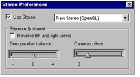
standard with Open Inventor. The range of values for the parallax balance and the camera offset is limited to what is usually used for comfortable viewing: from -1 to 3 for the parallax balance and from 0 to 2 for the offset. The application interface has no such limitations.
All viewers have the capability of setting all stereo parameters. They are the preferred way of accessing stereo. Note that the application interface for stereo also accepts calls made for the older stereo model. Both are discussed here.
The first step when setting the stereo is to specify the type of stereo to use:
C++ :
C# :
Java :
Again, SoBaseStereo is the base class for all stereo classes. For instance, to set the stereo viewing type to fast horizontal interleaved mode:
C++ :
C# :
Java :
Then, set the adjustment for the parallax balance and for the camera offset. This usually does not need to be modified since both of them are automatically computed according to the current view volume.
C++ :
C# :
C# :
Java :
The following step actually activates the stereo. Until this call, rendering is still in monoscopic mode.
C++ :
C# :
This call forces the render operation to go through the stereo object render code. The stereo object will then be able to set the camera to the correct stereo mode and render each view.
Deactivating stereo requires only one call:
C++ :
C# :
As the viewer is still set to a specific type of stereo with the specific stereo parameter values, reactivating the stereo only requires calling setStereoActive(TRUE).
Other methods of the viewer on the described stereo model apply but they will be discussed in the section called “ SoStereoViewer”.
To insure backward compatibility with older Open Inventor versions, and specifically with the old stereo model, the following methods still apply to stereo:
C++ :
C# :
About the old stereo model:
Like the current stereo model, the old model makes use of an offset to represent the eye separation. However, instead of adapting the view volume, the cameras were rotated toward the default point of focus, creating the stereo viewing angle.
If no type of stereo (from the current stereo model) is set on the viewer and setStereoViewing() is called, then the old stereo model is in effect. Note that setStereoViewing() is the method that actually sets OpenGL in stereo mode. If the old stereo model is in effect, then the offset passed to setStereoOffset() is no longer a factor but the actual value used to separate the cameras. In that case, the default value for the offset is 3.