|
Open Inventor Release 2024.2.3
|
|

| |
|
Open Inventor Release 2024.2.3
|
|
|
| |
Even though you do not need to be a professional C++ developer, you do need to know a little about C++ to use this library. Here are some concepts you must know before going any further. Before using any MeshViz nodes, as in Open Inventor, you must create an instance of the node. Because each of the new nodes is going to be stored in a scene graph, these nodes must exist for as long as they are used in the scene graph. This means that you cannot allocate a new node the scope of which does not fit the scene graph life-time. For instance, the following function is wrong since the scope of the myRectangle node is only within the CreateRectangle function. The reference to this node will no longer exist outside this function:
 A good habit to adopt with MeshViz nodes, as with Open Inventor nodes,
is to create a dynamic instance of the node each time you need a new one, using the C++ new operator.
You must not use the C++ delete operator because Open Inventor does the deletion when necessary (see the section called “Reference Counting” in The Inventor Mentor for a complete explanation of reference counting). A correct function to create and add a rectangle to the scene graph should look like this:
Once you have created a node, you may want to initialize or set the parameters that define the node. For a rectangle, for example, you may want to specify the two points that define the diagonally opposite corners of rectangle. There are several ways to do this. Some of the parameters may be initialized within the constructor of the class:
Using this method is not mandatory. To set any of the fields of a node,
you can use any of the standard Open Inventor methods setValue
,setValues
,set1Value or the = operator, depending on the field type.
Most of the GraphMaster and 3DdataMaster nodes are actually Open Inventor node kits. A node kit defines a collection of nodes that are automatically created by the kit on an as-needed basis. See Node Kits in The Inventor Mentor for an explanation of node kits.
As with Open Inventor, we distinguish property classes and visualization (or shape) classes. Property classes do not draw anything but are used by visualization classes. Visualization classes realize the drawing using property classes.
As described before, visualization classes depend on property classes for their appearance, to retrieve data, and so forth.
There are two ways to define these properties:
 Throughout this manual, you will see the preprocessor definition
“USE_PB” used in the source code of tutorials to show the use of these two types of property
classes.
All basic Pb[xxx] types in GraphMaster and 3DdataMaster are derived from the PbBase class. This class handles a connection mechanism that allows visualization Po[xxx] objects to be informed of any change happening in one of their fields, the type of which is derived from PbBase . This mechanism allows for the automatic updating of the visualization when any of the objects derived from PbBase is changed. For instance, PbMiscTextAttr basic types allow for the definition of miscellaneous text attributes, such as the text font. PoAxis is the basic class for all axis nodes. The following example creates an angular axis and sets the font to be used to draw a text string associated with the axis:
Anytime later, the font can be changed by calling the setFontName() method and the myAxis object will be informed automatically of this change and will update its visualization. The following call will change the display of the axis to use the Helvetica font instead of the Courier font:
This connection mechanism is activated by default. You can turn it on and off by calling the enableConnection() method inherited from the PbBase class. For instance, the following line will deactivate the default connection mechanism for the PbMiscTextAttr object; connected objects will not be informed of any changes to it:
Updating of connected objects can be forced by calling the touch() method inherited from the PbBase class. The following code will force all objects connected to the PbMiscTextAttr object to be updated:
The isConnectionEnabled() method can be used to find out if the connection mechanism is active for a specific instance of a PbBase or derived object. You must be careful with the use of local variables. Consider the following example:
Note that MeshViz node kits are built when it is necessary, that is, when an action occurs. Furthermore a Pb[xxx] object informs connected Po[xxx] objects of any change if the connection mechanism is active. However, even if the connection mechanism is inactive, Po[xxx] objects are informed of the delete of a Pb[xxx] object which is connected to them in order to maintain the integrity of data. In the previous example, the variable textAttr will be deleted at the end of the function buildAxis, so the axis object will be informed of this delete and, when it is built, the Utopia-Regular font (default font) will be used instead of the Courier font. (When a Po[xxx] object is not connected to a Pb[xxx] object, the values of the default constructor of the Pb[xxx] class are used.)
In the previous example, there are three solutions to solve this problem:
The copy constructor and assignment operator of any Pb[xxx] object do not copy the reference to Po[xxx] objects. This restriction prevents several Pb[xxx] objects (of the same class) from referencing the same Po[xxx] object.
The advantage of using Pb[xxx] classes is non-duplication of data for classes derived from PbMesh.
The main disadvantage is that these properties are not
written into .iv files and these objects must be deleted when they are no longer needed
(unlike property nodes).
MeshViz property node classes (available since version 3.5) must be used as Open Inventor property nodes classes (SoMaterial, SoDrawStyle, SoCoordinate3, etc.). These nodes are placed in the scene graph and when they are traversed, they replace the values in a corresponding element of the traversal state with their own values.
For instance, PoMiscTextAttr basic types allow for the definition of miscellaneous text attributes, such as the text font. PoAxis is the basic class for all axis nodes. The following example creates an angular axis and sets the font to be used to draw a text string associated with the axis:
Example : Use of PoMiscTextAttr property node
GraphMaster and 3DdataMaster visualization classes are implemented using the Open Inventor node kit facility, that is they all derive from the node kit base class SoBaseKit . This means that each new MeshViz node is a collection of Open Inventor nodes. The reference manual gives you a description of the parts (catalog parts ) for each node kit. You can access these parts to change the appearance of a node or the appearance of a part of the node kit. In this way, you can, for example, control the color of the arrow at the end of an axis or change the way you want to draw a rectangle, by drawing only the edges in red or applying a texture to it. The following example creates a transparent red-filled rectangle by changing the values of the appearance part of the PoRectangle node kit:
Example : Use of PoRectangle visualization class
It is also important to know that all MeshViz node kits are built only
when required, that is when any action causes them to be traversed. For instance, in the
previous example, the catalog part containing the shape node used for the rectangle is
updated (the part rectangle is updated; before the first rebuild this part is NULL) when a
render action traverses this node (that is, just the node is drawn), and also when a
bounding box action, callback action, etc. traverses it.
 In the following chapters, we will use the words “visualization node,”
“visualization class,” and “representation class,” as generic terms for nodes and node kits,
but always keeping in mind that all GraphMaster and 3DdataMaster extensions are, in fact,
node kits.
All MeshViz nodes are derived from the PoBase class. The init() static method of PoMeshViz::init() must be called before any other call to MeshViz. This method initializes the visualization database, registering all node kits and starting the connection mechanism. You must have the following line in all of your MeshViz applications:
The setNodeWriteFormat() static method selects the way node kits are stored on disk when using the Open Inventor SoWriteAction. Folded or unfolded storage of the node kit can be selected. Unfold format is required if you want to be able to share this output with a standard .iv browser Fold format is the default. The following code specifies the unfolded output format:
The following GraphMaster program will output two different .iv files (listed after the program) depending on whether UNFOLD or FOLD is specified.
Example : Generate an output file rectangle.iv with unfolded format
Example : Output file rectangle.iv with unfolded output
Example : Output file rectangle.iv with folded output
Inherited from PoBase , the setUpdateMethod() allows you to control updating of GraphMaster and 3DdataMaster nodes. As with Open Inventor, a node may be updated each time one of its fields is changed. This may be time-consuming if several fields of a single node have to be edited before getting the expected result. This method lets you specify whether the object should be updated as soon as the node changes, or only when an explicit update is requested. The following code sets the update of the PoRectangle node to be automatic, each time one of its p or q fields is modified (this is not the default):
You can force an object to be updated by using the touchKit method; the isModified method can be called to determine if a node has been
modified and not yet updated.
MeshViz nodekits create Open Inventor nodes in order to realize their own representation. For instance, a PoPieChart nodekit (for building a pie chart) creates a list of SoFaceSet nodes for each slice of the pie chart and stores them in its catalog (see Node-Kit Catalog, page 363 of The Inventor Mentor).
If you need to consult these nodes, they must be available (i.e. have been created). This normally happens on the first traversal of the nodekit. The callback set by the PoBase::addPostRebuildCallback() method is called as soon as these nodes are available.
For instance, if you want to retrieve the SoFaceSet of the first slice you must do the following:
All nodes in a scene graph can be transformed, scaled, and translated. They are able to draw their own geometry using the parameters that define it. For instance, an axis is defined by a starting and a finishing point. Suppose you want to create a Cartesian Y axis ranging from 0 to 10 and another one ranging from -π to π, and you want labels and strings to be placed at tick intervals that are 5% of the axis length. If you were to build your axes directly this way, you would have two axes rendered on your screen with different origins, different lengths, and different text heights. Perhaps, instead you want two parallel Y axes displayed with the same length, with the same Y origin, and using the same text height. Domains solve this problem by defining an area or a volume into which the node geometry is transformed before being displayed. By applying this transformation, a heterogeneous domain will be transformed into a homogeneous space. This transformation is realized by an SoTransform node within the node kit and applies a scale factor on the X, Y, or Z coordinates depending on the type of transformation you choose. Some node fields are defined using the domain coordinates. For instance, the text height of axes or the arrow width at the end of an axis is defined as a percentage of the domain. You can choose the following types of transformations assuming dx, dy, and dz are the differences (xmax-xmin), (ymax-ymin), and (zmax-zmin), and that xmin, ymin, zmin, xmax, ymax, and zmax are the domain limits.
The setDomain method inherited from PoBase class or the PoDomain property node can be used to define a domain. The following example defines a 2D domain [0-10] × [0-20]. By default the method used is SCALE_X_FIXED, which means that a scale factor of 0.5 (which is 10./20.) will be applied to the Y coordinates. Then the resulting rectangle will be rendered as a square on the screen.
This rectangle problem could have easily been solved using an Open
Inventor SoTransform node without using the setDomain method or PoDomain node.
The purpose here is to explain how a domain transformation acts on a node and how to solve
basic “ratio” problems using the domain transformation.
Example : Set a domain transformation 
If we want to render the rectangle with the real ratio on the screen and the correct dimensions, we should have a scale of 1 for each coordinate. Setting a domain to be [0-20] × [0-20] will solve this problem and the following lines will render the rectangle as expected:
Example : Set a domain to retain the original aspect ratio 
Setting a domain may not be important if you only want to use one coordinate system. In the previous example, even if you had not set the domain (so the default domain and transformation method were used instead), your rectangle would have been rendered correctly. But real problems begin when you want to draw different visualizations with different “bounding boxes” and when you want to mix them on the screen.
Example : Use of domain to align two rectangles with different locations and dimensions 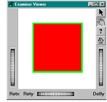 Now imagine we have two rectangles of different dimensions, and we want them to be rendered with the same size and in the same location on the screen. Here is a possible solution to this problem using domains:
Example : No domain use for both rectangles but SoTranslation node to the second rectangle 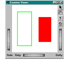
Example : Setting domains for the rectangles without translating the second one 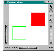
You can see here that translation has been computed to move the origin of the second rectangle to the first rectangle’s origin. The value 20 for translation on the X axis is obvious and the Y value is computed as follows:
What about mixing MeshViz nodes with Open Inventor nodes when we are
using the domain facilities? The setDomain method does not exist for SoBase -derived objects, thus MeshViz provides you with a method
to retrieve the SoTransform node used for the domain transformation inside the node
kit. Then this transformation can be applied to the Inventor nodes you want to mix with
MeshViz.
Example : Mixing use of PoRectangle and SoSphere 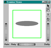
Example : TRANSFORM_01 method to maintain the sphere’s aspect ratio 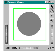 Using this transform method, the rectangle is projected to a [0,1] × [0,1] × [0,1] space.
Domain facilities provided inside MeshViz are very important for drawing
multiple axis systems. Once again, the previous example could have been much more easily
implemented without using domain facilities. Just remember that the default domain
transformation is the identity matrix and that no scaling or translation are applied to your
nodes.
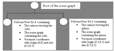
MeshViz provides an elegant way to specify several cameras in the same scene graph. The PoSceneView nodekit offers this capability.
A PoSceneView is defined by a camera, a viewport specified in normalized window coordinates, and a scene graph. This allows each PoSceneView to work in its own world coordinates.
As usual, the viewer will attach to the first camera it finds in the scene graph. You can also switch the viewer from one camera to another by calling SoXtViewer::setCamera(). There is no automatic mechanism to switch the viewer from one PoSceneView ’s camera to another.
The following figure illustrates the use of PoSceneView :
 The associated scene graph is: