|
Open Inventor Release 2024.2.0
|
|

| |
|
Open Inventor Release 2024.2.0
|
|
|
| |
Once all the required interface methods have been implemented in your application’s classes to define the mesh, you are ready to create graphical representations or to perform extractions to do, for instance, additional computations on the result. See Mesh Extraction for more details on using the extraction mechanism directly without using the data mapping nodes.
Data Mapping creates a graphical representation of a mesh or of the result of an extractor. The data mapping tools are Open Inventor extension nodes taking full advantage of the advanced rendering techniques provided by Open Inventor.
There are two levels of Open Inventor nodes:
The easiest way to display the result of an extract is by using the high-level containers. So we will first explain how to use these classes in the context of an Open Inventor program and then we will give more detailed explanations of the low level rendering tools.
Before going any further, your application must have implemented one of the mesh interfaces in your mesh classes as described above.
In this chapter we assume that you are familiar with the Open Inventor toolkit.
Before using any of the data mapping classes, the MeshViz Data Mapping toolkit must be initialized by calling the following static method:
Similarly, before ending the program, call the following method:
This deletes all allocated memory and cleans-up all the resources used.
 MoMeshViz::init() initializes the MeshViz Extraction toolkit, the OpenInventor database and all the related extensions necessary. Thus it is not necessary to call MiMeshViz::init() before calling MoMeshViz::init().
Mesh attributes are nodes that must be added to the scene graph and that are accumulated into the traversal state when an action is applied to the scene graph.
The MoMesh node stores a pointer to the object implementing the mesh interface. It must be set in the scene graph before any data mapping node. There are two different usages of MoMesh. The first one is simply passing the pointer to a user defined mesh to the node. This is the setMesh method.
The second one allows you to use the result of a previous representation as the input mesh. This is the connectFrom method.
The MoMesh::setMesh method:
This method is used to store a mesh in the scene graph. The same node is used for storing all types of mesh. This is done by providing one setMesh method for each type of mesh. The following code shows how to use it:
Where myMesh is the object implementing the mesh interface and root is an SoSeparator (or SoGroup) containing the scene graph.
When traversed, this node enables the MoMeshElement state element which is then used by data mapping nodes for retrieving the mesh to use.
The mesh is not stored as an Open Inventor field (SoField) object because doing so would not bring any benefit from the field functionality and would require creating one field type for each mesh type.
Most representations use a mesh extractor internally. This extractor usually creates a mesh of lower or equal dimension. It is sometimes necessary to use this resulting mesh as the input mesh for another representation. The connectFrom method can be used for that. Its parameter is a mesh representation node from which you want to compute another representation.
For instance, displaying isolines on top of an isosurface can be done this way:
Where myMesh is the object implementing the mesh interface and root is a SoSeparator (or SoGroup) containing the scene graph.
When traversed, this node enables the MoMeshElement state element which is then used by data mapping nodes for retrieving the mesh to use.
If the representations using the connected mesh specify a scalar or vector set identifier for coloring or any other usage, it must refer to the original data sets stored in the scene graph. The extraction of these data sets from the connected extractor (here the isosurface) will be performed automatically.
Scalar sets are stored in the scene graph using one of the MoScalarSetI, MoScalarSetIj or MoScalarSetIjk nodes depending on the type of scalar set. As several scalar sets can be used for the same extraction, the scalar sets are accumulated into the traversal state in an ordered list. Notice that there is one list for each type of scalar set described above. This is necessary because some algorithms will need MiScalardSetI scalar set in some cases and MiScalardSetIjk in other cases. Thus, for each list, the first created scalar set has index 0, the second has index 1 and so on.
Data mapping nodes use this index for retrieving the scalar set to use, for instance, for coloring a surface.
The following code shows how to store three scalar sets in the scene graph:
The first scalar set scalarSetI1 will have index 0 and the second scalarSetI2 will have index 1 in the list of MiScalardSetI elements. The third scalar set scalarSetIjk will have index 0 in the list of MiScalardSetIjk elements.
Vector sets are stored in the scene graph using one of the MoVec3SetI, MoVec3SetIj or MoVec3SetIjk nodes depending on the type of vector set.
Similar to scalar sets, the vector sets are accumulated into the traversal state in an ordered list. Notice that there is one list for each type of vector set described above. This is necessary because some algorithms will need MiVec3dSetI in some cases and MiVec3dSetIjk in other cases. Thus, for each list, the first created vector set has index 0, the second has index 1 and so on. Data mapping nodes use this index for retrieving the vector set to use.
The following code shows how to store three vector sets in the scene graph:
The first vector set vec3SetI1 will have index 0 and the second vec3SetI2 will have index 1 in the list of MiVec3dSetI elements. The third vector set vec3SetIjk will have index 0 in the list of MiVec3dSetIjk elements.
The MoDataBinding node can be used to force the data binding per cell or per node when it cannot be automatically detected from the data sets available in the traversal state list. This happens when using hexahedron IJKmeshes which support:
The MoCellFilter node stores a pointer to the object implementing the cell filter interface. It must be set in the scene graph before any data mapping node. The same node is used for storing all types of cell filter. This is done by providing one setCellFilter method for each type of mesh.
The following code shows how to use it:
Where myCellFilter is the object implementing the mesh interface and root is an SoSeparator ( or SoGroup) containing the scene graph.
When traversed, this node enables the MoCellFilterElement state element which is then used by data mapping for filtering extractions.
Color mapping means computing a color from a scalar value. This color can then be applied on top of a surface to visualize a scalar set. The color mapping nodes provide an easy way to define a color look-up table. Four types of color mapping nodes are provided.
+ GREY
+ TEMPERATURE
+ PHYSICS
+ STANDARD
+ GLOW
+ BLUE_RED
+ SEISMIC
+ BLUE_WHITE_RED
+ INTENSITY
The MoLegend node displays a colored legend of the current colormap in a rectangle. A name can be assigned to the legend. Min and max values can be set and a list of values can be displayed. The legend can be horizontal or vertical. The colormap node it represents must be stored in the scene graph before the legend node.
When surfaces are drawn using color contouring (see MoMaterial), each facet of a surface mesh is rendered using OpenGL. For faces with more than three points, OpenGL automatically converts the faces into triangles and performs color interpolation on each triangle individually without taking into account the other vertices and colors of the face.
In the following example, we have created four squares forming a regular mesh with data on each node. The center node as well as all corner nodes have value 1. The other nodes have value 0. On the right side, you can see that the OpenGL coloring shows an orientation of the data field which is not correct. Furthermore, the color at the center of the cell can be 0 or 1 depending on the way the cell is defined.
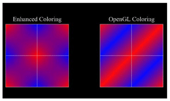
Enhanced coloring uses a GLSL shaders to perform the correct color interpolation. It may be time consuming on some graphic boards so it is disabled by default.
You should turn enhanced coloring on in the following conditions:
Enhanced coloring uses a GLSL shaders to perform the correct color interpolation
C++ :
In order to build a scene graph that can visualize a non linear mesh, an Open Inventor node of type MoMesh must be inserted into the scene graph. The method MoMesh::setMesh must refer to an unstructured mesh implementing the MiVolumeMeshUnstructured interface (for 3D mesh), MiSurfaceMeshUnstructured interface (for 2D mesh), or MiLineMeshUnstructured interface (for 1D mesh). This implementation must follow the rules described in Implementation of the MiCell interface to define a non linear mesh.
To visualize a non linear mesh, the scene graph must also contain an Open Inventor node of type MoTessellator so that it can handle correctly this type of meshes. 2 types of tessellators are provided by 2 factory methods in MiTessellator :
MiTessellator::getNewTessellatorBasic ();
MiTessellator::getNewTessellatorGeometry(edgeMetric);
The rendering quality can be tuned by the given argument edgeMetric. Code example to visualize the tessellated skin of a non linear mesh with the geometric tessellator.
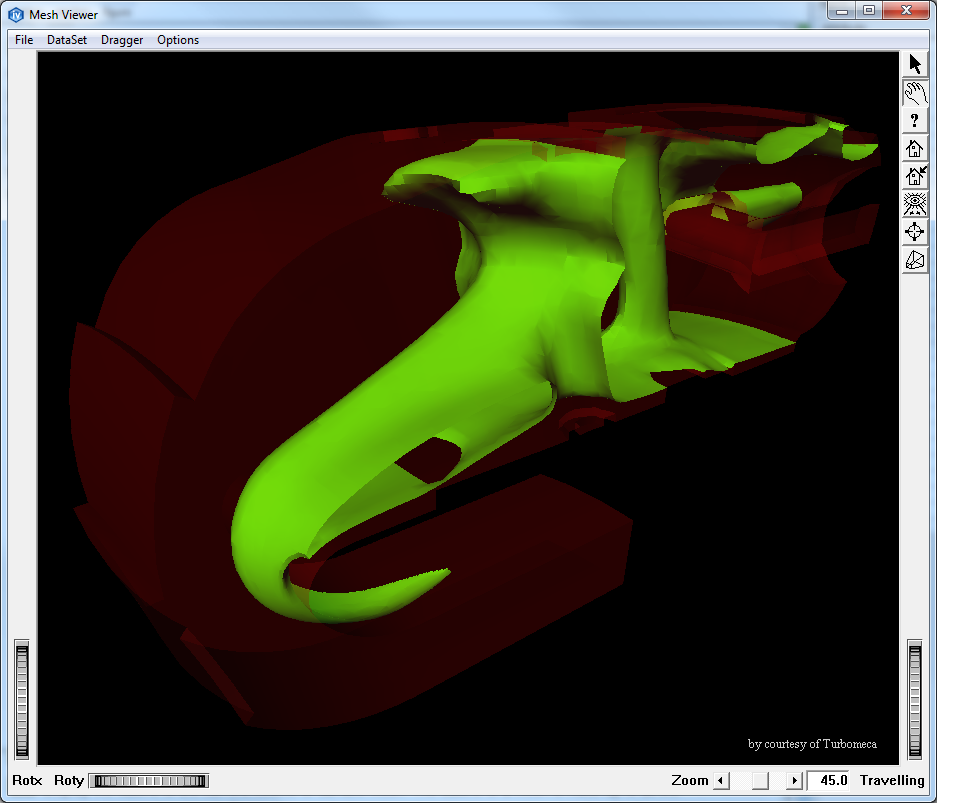
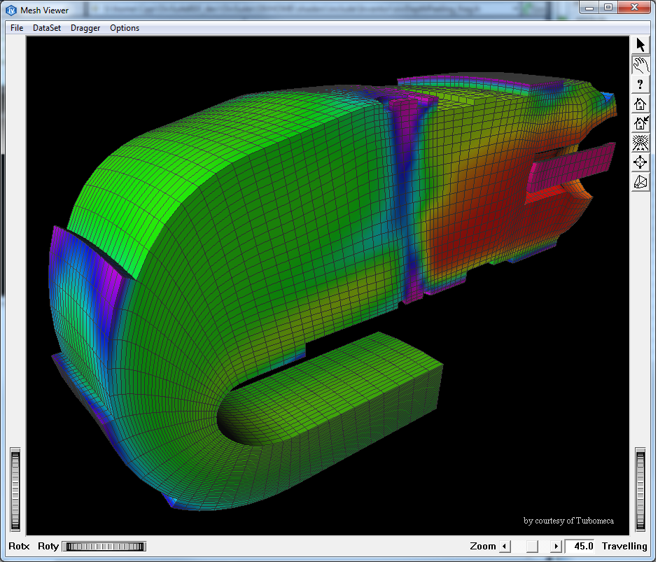
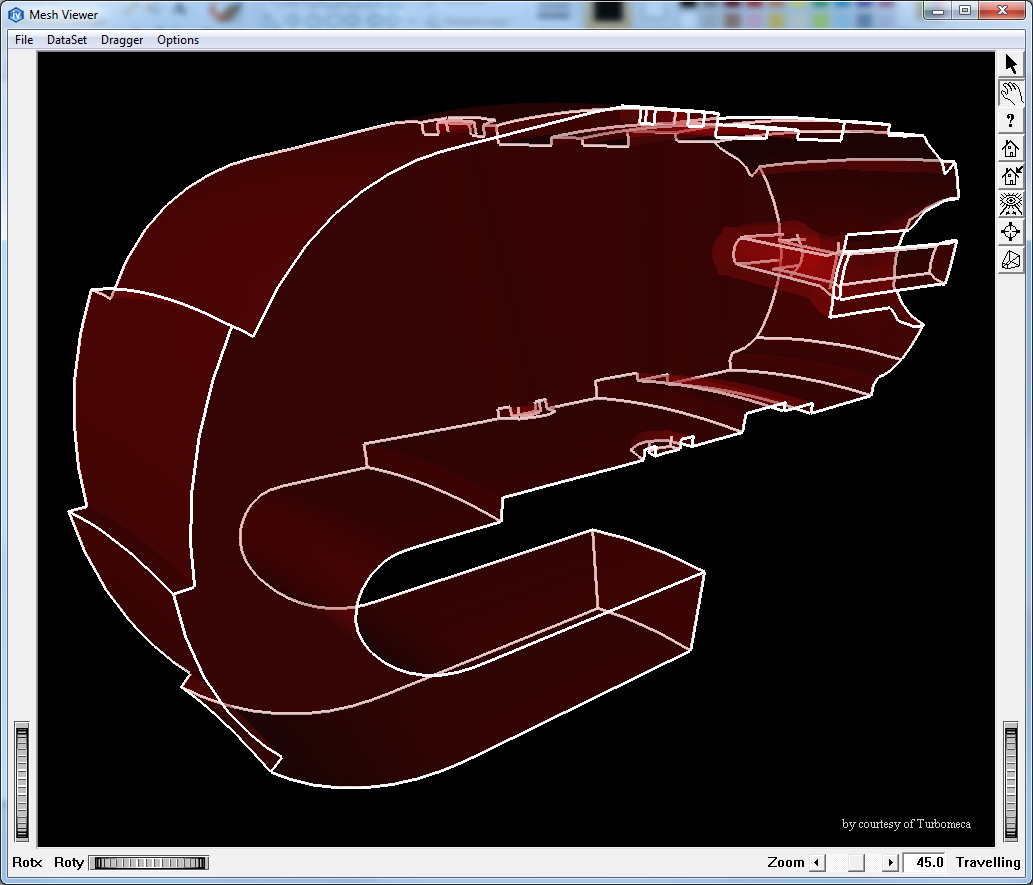
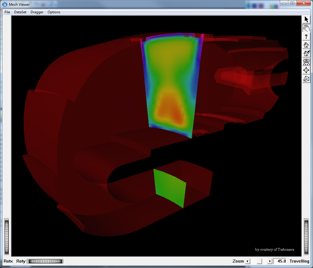
The following screen shots shows an example of rendering the skin of a non linear synthetic mesh with a basic tessellator and with a geometrical tessellator
Generally MeshViz XLM is able to handle polyhedral meshes (see definition in Support of polygonal surface meshes and polyhedral volume meshes). However in order to build a scene graph that visualizes an isosurface from a polyhedral mesh, the Open Inventor node MoTessellator must be inserted into the scene graph before the MoMeshIsosurface node.
A polyhedron tessellator must be given to the MoTessellator as follows:
In the same way the node MoTessellator is also required for visualizing any slice such as MoMeshPlaneSlice, MoMeshSphereSlice or MoMeshCylinderSlice.
Once the mesh, the scalar sets, vector sets, cell filter and color mapping attribute nodes are contained in the scene graph as described above, we can use the mesh representation nodes to visualize some mesh properties such as isosurface, mesh skin, etc.
All mesh representation nodes inherit from the abstract MoMeshRepresentation node. They inherit several fields and methods common to all representations decribed below.
The MoMeshRepresentation is derived from MoMeshBaseRepresentation which manages actions on Meshviz Data Mapping nodes.
The color scalar set identifier colorScalarSetId field represents the scalar set node to be used to map colors onto the representation. By default, colorScalarSetId is set to 0 which represents the first scalar set in the list of current scalar set nodes of the scene graph.
To disable coloring for a node, just set this field to -1.
The parallel field can be used to turn on or off specific optimizations to take advantage of multi processor systems during the extraction process. Some extraction algorithms such as skin or grid plane slice are already optimized to take advantage of multi processor systems. More optimizations will be provided in future versions. The parallel flag is on by default.
The Intel Threading Building Blocks (TBB) API is used internally to perform some of the optimizations on compatible systems. TBB can be used with other multi threading tools like OpenMP for instance. The parallel field can be turned off to avoid any conflict with other parallel programming techniques
Mesh representations perform an extraction whenever a change is detected in the mesh, in the scalar set or int the cell filter stored in the scene graph. This extraction may take some time and thus it may be necessary to catch these events in order to manage a progress bar or to display a hour glass cursor or just to display a status message. To do so use the MoMeshRepresentation::setExtractorCallback() method by passing a class derived from MiExtractorCallback.
The method MiExtractorCallback::beginExtract() and MiExtractorCallback::endExtract() are called respectively before and after a new extraction.
Furthermore, the most cpu intensive extractions (like isosurface, slice or skin extraction) are conceptually divided in several phases and each phases are divided in several steps. The number of phases is given by the last argument of the method beginExtract(). The number of steps in a phase is given by the last argument of the method beginPhase(). If the number of phases is > 0, the methods beginPhase/*endPhase* are called at the beginning/end of a phase. The method endStep() is called when a certain amount of jobs in the phase is achieved. All these methods allow the application to implement and animate a progress bar (using either a single or multiple bars).
The Open Inventor render cache is a sophisticated mechanism which can redraw the children of a SoSeparator without having to traverse them. For MeshViz XLM mapping nodes, this means that this mechanism may prevent the MoMeshRepresentation derived nodes from detecting changes in the interface they are monitoring.
When a MoMeshRepresentation node is traversed, the node checks the time stamps of the interfaces (mesh, dataset, cell filter, tessellator) that it depends on. However changing for instance a cell filter in the application and modifying its time stamp (in the MiCellFilter interface) does not produce any event in the Open Inventor kernel to trigger an update. Thus this node could not be traversed because of render caching and the representations could not be updated.
To avoid this problem, we recommend to just call the touch method of one the MeshViz XLM nodes depending on this change. In the case described above, call MoCellFilter::touch() after changing the cell filter time stamp.
Display the current line mesh as a line set. The lines can be colored using a scalar set defined in the colorScalarSetId inherited field.
Display the current surface mesh as a face set. The faces can be colored using a scalar set defined in the colorScalarSetId inherited field.
Display an isosurface on a scalar set extracted from the current volume mesh. The surface is made up of points having the given value in the given data set. The scalar set used to extract the isosurface is defined by the isoScalarSetId field. This is an index into the list of scalar set elements existing in the traversal state. See the section called “Scalar Set nodes” for more details on indexing scalar sets. The isosurface created can be colored using another scalar set defined in the colorScalarSetId inherited field.
The MoMeshIsosurface node creates an isosurface extractor to compute the isosurface. This extractor can be retrieved by calling the get*Extractor() method corresponding to the type of mesh stored in the scene graph. For instance, when creating an unstructured mesh, the MiIsosurfExtractUnstructured extractor can be retrieved by calling getUnstructuredExtractor().
This allows you to retrieve the result of the extract performed internally by the MoMeshIsosurface node to use it, for instance, as input to another extraction module. See the section called “Isosurface on a scalar data set ” for more details.
Display the skin of the current volume mesh. The skin of a mesh is made up of all the faces that belong to only one cell. The skin created can be colored using a scalar set defined in the colorScalarSetId inherited field.
The MoMeshSkin node creates a skin extractor to compute the mesh skin. This extractor can be retrieved by calling the get*Extractor() method corresponding to the type of mesh stored into the scene graph. For instance, when creating an unstructured mesh, the MiSkinExtractUnstructured extractor can be retrieved by calling getUnstructuredExtractor().
This allows you to retrieve the result of the extract performed internally by the MoMeshSkin node to use it, for instance, as input to another extraction module. See the section called “Mesh skin” for more details.
Display the outline of the current volume or surface mesh. The outline of a mesh is made up of all the edges that belong to only one cell. The outline created can be colored using a scalar set defined in the colorScalarSetId inherited field.
The MoMeshOutline node creates a outline extractor to compute the mesh outline. This extractor can be retrieved by calling the get*Extractor() method corresponding to the type of mesh stored into the scene graph. For instance, when creating an unstructured mesh, the MiOutlineExtractUnstructured extractor can be retrieved by calling getUnstructuredExtractor().
This allows you to retrieve the result of the extract performed internally by the MoMeshOutline node to use it, for instance, as input to another extraction module. See the section called “Mesh Outline” for more details.
Display a logical slice extracted from the current IJK volume mesh. A logical slice is defined by an axis (I, J or K) and an integer sliceIndex. The logical slice created can be colored using another scalar set defined in the colorScalarSetId inherited field.
The MoMeshLogicalSlice node creates a logical slice extractor to compute the logical slice. This extractor can be retrieved by calling the get*Extractor() method corresponding to the type of mesh stored in the scene graph. For instance, when creating a regular mesh, the MiLogicalSliceExtractRegular extractor can be retrieved by calling getRegularExtractor().
This allows you to retrieve the result of the extract performed internally by the MoMeshLogicalSlice node to use it, for instance, as input to another extraction module. See the section called “Logical slice” for more details.
Display an interpolated logical slice extracted from the current IJK volume mesh. An interpolated logical slice is defined by an axis (I, J or K) and a floating point sliceValue. The interpolated logical slice created can be colored using another scalar set defined in the colorScalarSetId inherited field.
The MoMeshInterpolatedLogicalSlice node creates an interpolated logical slice extractor to compute the interpolated logical slice. This extractor can be retrieved by calling the get*Extractor() method corresponding to the type of mesh stored in the scene graph. For instance, when creating a regular mesh, the MiInterpolatedLogicalSliceExtractRegular extractor can be retrieved by calling getIjkExtractor().
This allows you to retrieve the result of the extract performed internally by the MoMeshInterpolatedLogicalSlice node to use it, for instance, as input to another extraction module. See the section called “Interpolated Logical slice” for more details.
Display a plane slice extracted from the current volume mesh. A plane slice is defined by an arbitrary plane in 3D (SbPlane). The plane slice created can be colored using a scalar set defined in the colorScalarSetId inherited field.
The MoMeshPlaneSlice node creates a plane slice extractor to compute the plane slice. This extractor can be retrieved by calling the get*Extractor() method corresponding to the type of mesh stored in the scene graph. For instance, when creating an unstructured mesh, the MiPlaneSliceExtractUnstructured extractor can be retrieved by calling getUnstructuredExtractor().
This allows you to retrieve the result of the extract performed internally by the MoMeshPlaneSlice node to use it, for instance, as input to another extraction module. See the section called “Plane Slice” for more details.
Display a fence slice extracted from the current volume mesh. A fence slice is defined by the intersection of several arbitrary planes (the fences). These fences are defined by the fields polyline and direction of the MoMeshFenceSlice class. Each segment of the polyline is extruded along the direction to form a clipped plane slice. Thus, each fence goes through a segment of the polyline. Each plane slice is clipped by the extrusion of the 2 endpoints of each segment in the direction. The fence slice created can be colored using a scalar set defined in the colorScalarSetId inherited field.
The MoMeshFenceSlice node creates a fence slice extractor to compute the fence slice. This extractor can be retrieved by calling the get*Extractor() method corresponding to the type of mesh stored in the scene graph. For instance, when creating an unstructured mesh, the MiFenceSliceExtractUnstructured extractor can be retrieved by calling getUnstructuredExtractor().
This allows you to retrieve the result of the extract performed internally by the MoMeshFenceSlice node to use it, for instance, as input to another extraction module.
Display a cylinder slice extracted from the current volume mesh. A cylinder slice is defined by an arbitrary cylinder in 3D (center position, radius and direction vector). The cylinder slice created can be colored using another scalar set defined in the colorScalarSetId inherited field.
The MoMeshCylinderSlice node creates a cylinder slice extractor to compute the cylinder slice. This extractor can be retrieved by calling the get*Extractor() method corresponding to the type of mesh stored in the scene graph. For instance, when creating an unstructured mesh, the MiCylinderSliceExtractUnstructured extractor can be retrieved by calling getUnstructuredExtractor().
This allows you to retrieve the result of the extract performed internally by the MoMeshCylinderSlice node to use it, for instance, as input to another extraction module. See the section called “Cylinder Slice” for more details.
Display a sphere slice extracted from the current volume mesh. A sphere slice is defined by an arbitrary sphere in 3D (center position and radius).
The sphere slice created can be colored using another scalar set defined in the colorScalarSetId inherited field.
The MoMeshSphereSlice node creates a sphere slice extractor to compute the sphere slice. This extractor can be retrieved by calling the get*Extractor() method corresponding to the type of mesh stored in the scene graph. For instance, when creating an unstructured mesh, the MiSphereSliceExtractUnstructured extractor can be retrieved by calling getUnstructuredExtractor().
This allows you to retrieve the result of the extract performed internally by the MoMeshSphereSlice node to use it, for instance, as input to another extraction module. See the section called “Sphere Slice” for more details.
Display a grid plane slice extracted from the current volume mesh. A grid plane slice is similar to a plane slice but the generated plane is a regular grid on which nodes are evaluated using the probing mechanism. The grid plane slice created can be colored using another scalar set defined in the colorScalarSetId inherited field.
The MoMeshGridPlaneSlice node creates a plane slice extractor to compute the plane slice. This extractor can be retrieved by calling the get*Extractor() method corresponding to the type of mesh stored in the scene graph. For instance, when creating an unstructured mesh, the MiGridPlaneSliceExtractUnstructured extractor can be retrieved by calling getUnstructuredExtractor().
This allows you to retrieve the result of the extract performed internally by the MoMeshGridPlaneSlice node to use it, for instance, as input to another extraction module. See the section called “Grid Plane Slice” for more details.
Display an elevated plane slice extracted from the current volume mesh. An elevated plane slice is created by extracting a plane slice of the current volume mesh and displaying a volume defined by the elevation of this slice. The plane slice extracted is defined by an arbitrary 3D plane (SbPlane) specified in the plane field. The elevation values are defined using a scalar set defined in the elevationScalarSetId field and can be scaled by the value specified in the scaleFactor field. The volume displayed can be colored using another scalar set defined in the colorScalarSetIdinherited field.
The MoMeshElevatedPlaneSlice node creates a plane slice extractor to compute the plane slice. This extractor can be retrieved by calling the get*Extractor() method corresponding to the type of mesh stored in the scene graph. For instance, when creating an unstructured mesh, the MiPlaneSliceExtractUnstructured extractor can be retrieved by calling getUnstructuredExtractor().
This allows you to retrieve the result of the extract performed internally by the MoMeshElevatedPlaneSlice node to use it, for instance, as input to another extraction module.
Display a set of isolines extracted from the current surface mesh.
The isolines created can be colored using another scalar set defined in the colorScalarSetId inherited field. You can specify the iso values, the period of major contour lines and line patterns for major and minor contour lines.
The MoMeshIsoline node creates an isoline extractor to compute the isolines. This extractor can be retrieved by calling the get*Extractor() method corresponding to the type of mesh stored in the scene graph. For instance, when creating an unstructured mesh, the MiIsolineExtractUnstructured extractor can be retrieved by calling getUnstructuredExtractor().
This allows you to retrieve the result of the extract performed internally by the MoMeshIsoline node to use it, for instance, as input to another extraction module. See the section called “Isolines” for more details.
Display a set of isolines with annotations extracted from the current surface mesh. The isolines created can be colored using another scalar set defined in the colorScalarSetId inherited field. Several parameters control the way annotation text is displayed.
The MoMeshAnnotatedIsoline node creates an isoline extractor to compute the isolines. This extractor can be retrieved by calling the get*Extractor() method corresponding to the type of mesh stored in the scene graph. For instance, when creating an unstructured mesh, the MiIsolineExtractUnstructured extractor can be retrieved by calling getUnstructuredExtractor().
This allows you to retrieve the result of the extract performed internally by the MoMeshAnnotatedIsoline node to use it, for instance, as input to another extraction module. See the section called “Isolines” for more details.
Display a clip line extracted from the current surface mesh. A clip line is defined by the intersection of an arbitrary plane in 3D (SbPlane) with the surface.The plane is specified in the plane field. The created clip line can be colored using a scalar set defined in the colorScalarSetId inherited field.
The MoMeshClipLine node creates a clip line extractor to compute the clip line. This extractor can be retrieved by calling the get*Extractor() method corresponding to the type of mesh stored in the scene graph. For instance, when creating an unstructured mesh, the MiClipLineExtractUnstructured extractor can be retrieved by calling getUnstructuredExtractor().
This allows you to retrieve the result of the extract performed internally by the MoMeshClipLine node to use it, for instance, as input to another extraction module.
Displays a list of intersection points extracted from the current line mesh. The displayed points are defined by the intersection of an arbitrary plane (SbPlane) and the line.The plane is specified in the plane field. The created points can be colored by using a scalar set defined in the colorScalarSetId inherited field.
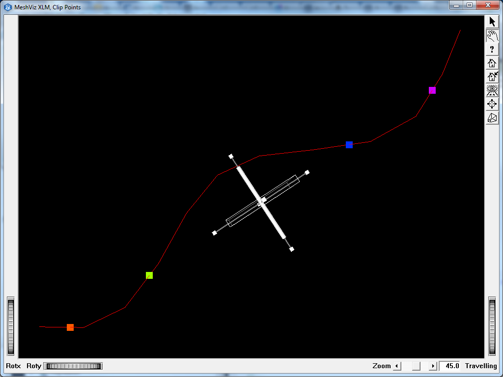
This allows retrieving the result of the extract performed internally by the MoMeshClipPoint node and then this result may be used for instance as input to another extraction module.
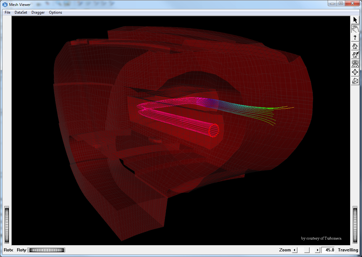
Display a set of stream lines extracted from the current volume mesh. The stream lines created can be colored using another scalar set defined in the colorScalarSetId inherited field.
The MoMeshStreamline node creates a stream line extractor to compute the stream lines. This extractor can be retrieved by calling the get*Extractor() method corresponding to the type of mesh stored in the scene graph. For instance, when creating an unstructured mesh, the MiStreamlineExtractUnstructured extractor can be retrieved by calling getUnstructuredExtractor().
This allows you to retrieve the result of the extract performed internally by the MoMeshStreamline node to use it, for instance, as input to another extraction module. See the section called “Stream lines from a vector field data set” for more details.
Display a vector data set as a set of arrow vectors. Each value of the vector data set is represented by a small arrow located at the cell center for per cell data sets or at the node position for per node data sets.
The vectorSetId field defines the index of the vector set to display. See the section called “Vector Set nodes” for more details on how to store a vector set in the scene graph.
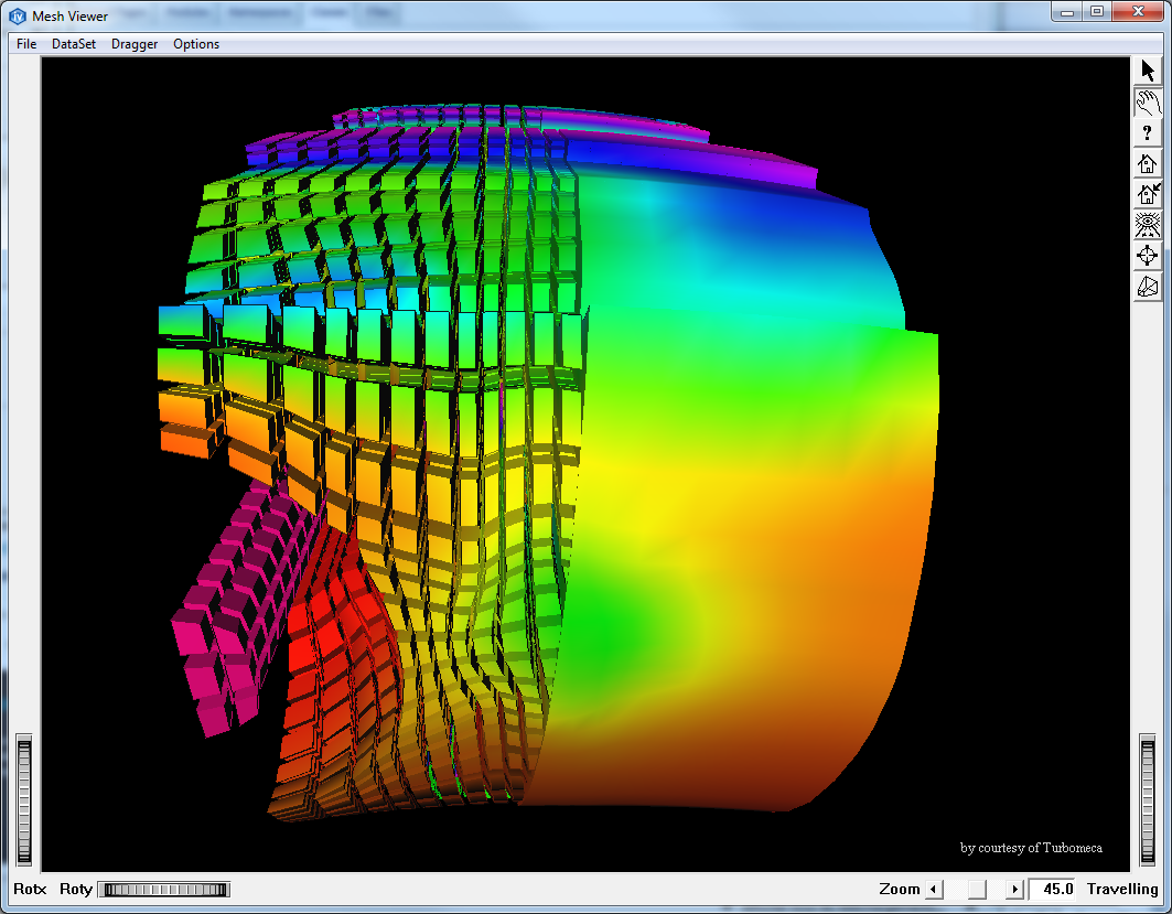
Display a subset of the mesh cells extracted from the mesh as surfaces. The surface created can be colored using another scalar set defined in the colorScalarSetId inherited field. The cell names and node names can be displayed near their position. Node names and cell names are defined in the topology interfaces. By default, they return the cell or node number. Cells can be rendered at their normal size or can be scaled to have a better understanding of their shape independently of their neighbors.
The MoMeshCellShape node creates a cell extractor to compute the cell surface. This extractor can be retrieved by calling the get*Extractor() method corresponding to the type of mesh stored into the scene graph. For instance, when creating an unstructured mesh, the MiCellExtractUnstructured extractor can be retrieved by calling getUnstructuredExtractor().
This allows you to retrieve the result of the extract performed internally by the MoMeshCellShape node to use it, for instance, as input to another extraction module. See the section called “Cell Extraction” for more details.
Low-level mesh representation nodes are nodes derived from MoMeshBaseRepresentation which simply draw the input mesh without adding any feature extraction as opposed to high-level nodes.
These nodes are used by all high level nodes to render the result of the extract they perform. They don’t get their parameters from the current state list like the high level nodes. They receive them by parameter. They are designed to be used by your own implementation of high level nodes to render the result of another custom extract.
This node displays a surface defined by any type of surface mesh interface (MiSurfaceMeshUnstructured, MiSurfaceMeshRegular, MiSurfaceMeshRectilinear or MiSurfaceMeshCurvilinear) colored using a given scalar set. Use the setSurfaceMesh method to set the mesh and the scalar set to be used for display. This node is used internally by the high-level mesh representation nodes for rendering the extracted surfaces they contain. It uses the time stamp mechanism to detect that the input mesh and data sets have changed to rebuild its internal caches.
This node displays a set of lines defined by any type of line mesh interface (MiLineMeshUnstructured, MiLineMeshRegular or MiLineMeshCurvilinear) colored using a given scalar set. Use the setLineMesh method to set the mesh and the scalar set to be used for display. This node is used internally by the high-level mesh representation nodes for rendering the extracted lines they contain. It uses the time stamp mechanism to detect that the input mesh and data sets have changed to rebuild its internal caches.