Non-Uniform Rational B-Spline curves and surfaces are very powerful methods for representing curves and surfaces in a parametric form. Instead of using hundreds of points to define a curve, a few control points and parameters can define a very clean curve that can be approximated using a variable number of points depending on the point of view.
Open Inventor displays NURBS curves and surfaces using the SoNurbsSurface( C++ | Java | .NET ) ,SoIndexedNurbsSurface( C++ | Java | .NET ) ,SoNurbsCurve( C++ | Java | .NET ) , and SoIndexedNurbsCurve( C++ | Java | .NET )nodes. NURBS surfaces can be trimmed, that is, cut like with scissors. Trim curves are defined using the SoProfile( C++ | Java | .NET )nodes. For more detailed information about NURBS, read Chapter 20, Curves and Surfaces of The Inventor Mentor.
NURBS surfaces are very often used by CAD systems to represent complex assemblies. A whole car can be made of several thousands of NURBS surfaces. When displaying this type of large object, Open Inventor draws the triangles generated by “tessellating” the NURBS object. That is, by transforming the NURBS equations into triangles. When rendering in shaded mode, Gouraud shading hides the individual triangles and the object looks smooth. But when displaying in wireframe mode, Open Inventor displays the edges of each triangle. Thus, for large models, the image can become overly complicated and difficult to interpret. Also, when displaying in wireframe mode, NURBS surfaces may look flat even if they aren’t. For large surfaces displayed in wireframe, drawing a single isoparametric curve in the middle of the NURBS improves the rendering quality.
Alternatively, it is sometimes interesting to see the edges of each trimmed surface by visualizing the trim curves and the surface boundaries on top of the shaded surface.
Adaptive tessellationis the ability to generate more (or fewer) triangles depending on the curvature of the NURBS surface. Regions of higher curvature can be more highly triangulated, regions of lower curvature, less triangulated. This allows higher quality rendering while still maintaining good performance.
The SoNurbsProperty( C++ | Java | .NET )node provides all these features.
SoNurbsProperty( C++ | Java | .NET ) has the following fields:
drawStyle (SoSFBitMask) | Specifies which part(s) of the NURBS to display:
Turning off the normal display and turning on display of trim curves, boundaries, and isoparametric curves, can dramatically speed up rendering of large models. | |||
numSamplePoints (SoSFInt32) | Specifies the number of sample points between trim curves control points. If this value is equal to -1 (the default), this number is computed from the SoComplexity( C++ | Java | .NET )node. It allows the number of triangles generated during trim curve tessellation to be decreased when this field is set to a small value (less than 3). This field is used for the drawStyle values NORMAL and BOUNDARIES_AND_TRIM_CURVES. | |||
color (SoSFColor) | Specifies the color used for rendering trim curves and isoparametric curves: BOUNDARIES_AND_TRIM_CURVES and CENTRAL_ISO_PARAM_CURVES | |||
isoParamCurvesPattern (SoSFUShort) | Specifies the line pattern used for rendering isoparametric curves. | |||
tessellationType (SoSFEnum) | Specifies the tessellation type:
| |||
tessellationDistance (SoSFFloat) | Used when tessellationType is set to ADAPTIVE. The maximum tessellation step size (curvilinear distance) is this fraction of the diagonal of the bounding box of the surface or the group of surfaces (SoNurbsGroup( C++ | Java | .NET )). Increasing this value make the tessellation more dependent on tessellationAngle. Default value is 0.01. That is, the distance must not be more than 1% of the diagonal of the bounding box. | |||
tessellationAngle (SoSFFloat) | Used when tessellationType is set to ADAPTIVE. Specifies the maximum angle (in radians) between the normals of two adjacent tessellated faces. Decreasing this value adds more tessellation points on flat parts of the surface. Default value is 0.35. |
![[Note]](../images/note.jpg)
Example 20.5. Using SoNurbsProperties
This example reads an Inventor file and inserts an SoNurbsProperty( C++ | Java | .NET ) node as the first child of the root if the file does not already contain such a node. The ‘B’, ‘I’, and ‘N’ keys allow the user to show/hide boundaries, isoparametric curves, and the NURBS surface respectively. The ‘M’ and ‘L’ keys can be used to increase or decrease the number of sample points between trim curve control points. The program source code is available in:$OIVHOME/src/Inventor/examples/Features/NurbsProperties/NurbsProperties.cxx
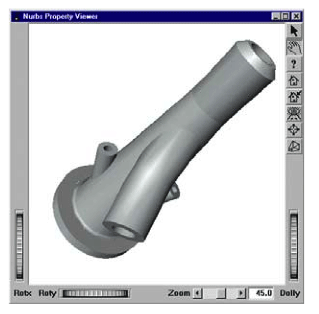 SoNurbsProperty::NORMAL |
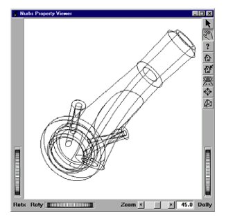 SoNurbsProperty::BOUNDARIES_AND_TRIM_CURVES |
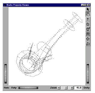 SoNurbsProperty::CENTRAL_ISO_PARAM_CURVES |
 SoNurbsProperty set to all of the above (using a bitmask) |
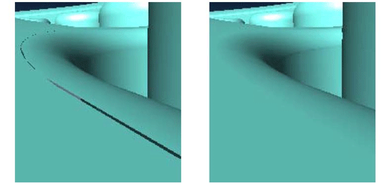
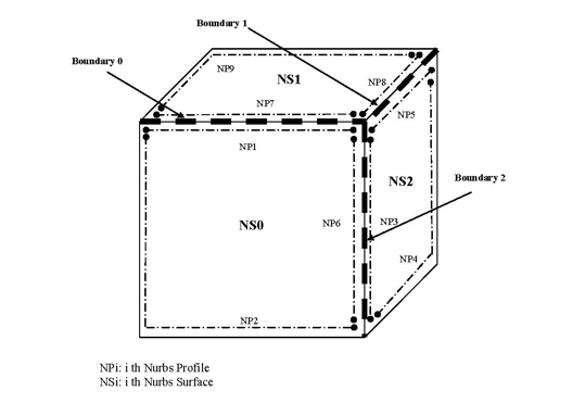
Sometimes when a collection of NURBS surfaces is used to define an object, “cracks” can appear between the edges of adjacent NURBS surfaces. In order to avoid this effect, the SoNurbsGroup( C++ | Java | .NET )and SoNurbsBoundary( C++ | Java | .NET )nodes, along with the boundary field of SoNurbsProfile( C++ | Java | .NET )can be used.
The surfaces to be joined must be under the same SoNurbsGroup( C++ | Java | .NET ) grouping node and must have profiles (SoNurbsProfile( C++ | Java | .NET )) that share the same boundary (SoNurbsBoundary( C++ | Java | .NET )).
The SoNurbsBoundary( C++ | Java | .NET ) node is used in the boundary field of SoNurbsProfile( C++ | Java | .NET ). When a surface is rendered, it will be joined along the profile(s) that it has in common with other surfaces in the group. See Figure 20.22, “ Joining three NURB surfaces along their common boundaries”.
Note that in order for this to work, profiles must have an equivalent parameterization. Evaluating two profiles with a shared boundary at the same t will give two (u, v) pairs: (u1, v1) and (u2, v2). Then, evaluating (u1, v1) on the first NURBS surface will give a point P1, and (u2, v2) will give a point P2 on the second surface. If P1 and P2 are equal (within a tolerance), then the two profiles have an equivalent parameterization.
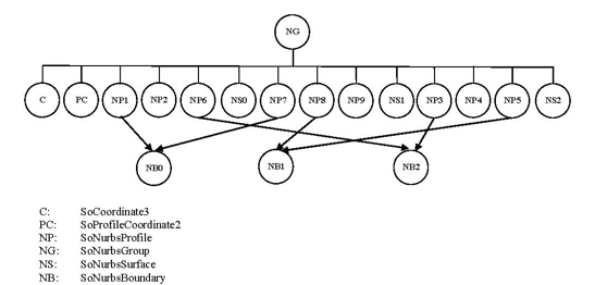
The corresponding scene graph structure is illustrated below.
The directory $OIVHOME/data/models/NurbsCrackFree contains models showing examples of NURBS crack-free tessellation. For each model there are three files:
A file containing the model with cracks
A file containing the model with no cracks
A file containing both versions of the model
Figure 20.24, “ NURBS surfaces with cracks (left) and no cracks (right)” below shows a close-up of one of the models (Enjoliver), with cracks and without.