This section outlines the basic sequence for initializing Inventor for use with the Xt Intrinsics, a library built on top of the X Window System library. An Xt widget contains an X window, along with extra functions for controlling the widget behavior. Because they contain a window, widgets can receive events from the X server.
The SoXt::init() routine returns an Xt widget that serves as the application's main shell window. In the following example, the widget is named myWindow. An SoXtRenderArea( C++ ) is later put into this window.
The basic steps are as follows:
Initialize Inventor for use with the Xt Intrinsics (SoXt::init()).
Create the SoXtRenderArea( C++ ).
Build other Inventor objects and Xt widgets.
Show the render area and Xt widgets (myRenderArea->show(); SoXt::show()).
Enter the event loop (SoXt::mainLoop()).
Here is an example that follows this sequence:
C++
#include <X11/Intrinsic.h>
#include <Inventor/So.h>
#include <Inventor/Xt/SoXt.h>
#include <Inventor/Xt/SoXtRenderArea.h>

main(int argc, char **argv)
{
   // Initialize Inventor and Xt
   Widget myWindow = SoXt::init(argv[0]);

   SoXtRenderArea *myRenderArea =
         new SoXtRenderArea(myWindow);

   SoSeparator *root = new SoSeparator;
   // Build other Inventor objects and Xt widgets
   // and set up the root
   // ...

   myRenderArea->setSceneGraph(root);
   myRenderArea->setTitle("Simple Xt");
   myRenderArea->show(); // this calls XtManageChild
   SoXt::show(myWindow); // this calls XtRealizeWidget

   // Realize other Xt widgets
   // ...

   // Go into main event loop
   SoXt::mainLoop();
}
The SoXtRenderArea( C++ ) is an Xt widget that performs OpenGL rendering. When it receives X events, it translates them into SoEvents, which are then passed to the scene manager for handling.
The scene graph to be rendered is set into the render area with the setSceneGraph() method. (This method increments the root's reference count.) The getSceneGraph() method returns the root node of this scene graph.
Other useful methods on SoXtRenderArea( C++ ) include the following:
specifies how transparent objects are rendered (see the section on the render action in Chapter 8, Applying Actions for details). | |
specifies the antialiasing methods. | |
shows or hides the window border. | |
specifies the window background color. |
The render area attaches a node sensor to the root of the scene graph and automatically redraws the scene whenever the scene graph changes. Use the following method to change the priority of the redraw sensor:
Use the following two methods if you wish to disable automatic redrawing:
enables or disables the redraw sensor on the render area. | |
redraws the scene immediately. If AutoRedraw is TRUE, you don't need to make this call. |
See the Open Inventor C++ Reference Manual on SoXtRenderArea( C++ ) for more information on these methods.
If you use the default values when you create an SoXtRenderArea( C++ ), mouse and keyboard events are handled automatically. The constructor for SoXtRenderArea( C++ ) is
SoXtRenderArea(Widget parent = NULL, const char * name = NULL, SbBool buildInsideParent = TRUE, SbBool getMouseInput = TRUE, SbBool getKeyboardInput = TRUE);
To disable input from either the mouse or the keyboard, specify FALSE for the getMouseInput or getKeyboardInput variable. For example, to disable mouse input:
C++
SoXtRenderArea *renderArea = new SoXtRenderArea(parent,
         "myRenderArea", TRUE, FALSE, TRUE);
Inventor defines three Xt devices:
Use the registerDevice() method to register additional devices, such as the spaceball, with the render area. When this method is called, the render area registers interest in events generated by that device. When it receives those events, it translates them into SoEvents and passes them to the scene manager for handling. For information on creating your own device, see The Inventor Toolmaker.
The overlay planes are a separate set of bitplanes that can be used for special purposes in Inventor. (Check your release notes for the number of overlay planes, which is implementation-dependent.) The overlay planes are typically used for objects in the scene that appear on top of the main image and are redrawn independently. Although you are limited with respect to color and complexity of the scene graph placed in the overlay planes, using them enables you to quickly redraw a simple scene graph without having to redraw the “complete” scene graph. The overlay planes provide a useful mechanism for providing user feedback—for example, for rapidly drawing geometry that follows the cursor.
Use the following methods to place a scene graph in the overlay planes:
sets the scene graph to render in the overlay planes | |
sets the colors to use for the overlay bit planes; the overlay planes usually use color-index mode | |
sets the index of the background color for the overlay image (the default is 0, the clear color) |
The overlay scene graph has its own redraw sensor and is similar to the “regular” scene graph, with these restrictions:
If you have a small number of overlay planes (for example, two), specify BASE_COLOR for the model field of SoLightModel( C++ | Java | .NET ). (If your implementation has more than two overlay planes, you may be able to obtain crude lighting effects by using the SoMaterialIndex node; otherwise, use the SoColorIndex( C++ | Java | .NET ) node to specify color indices.)
Keep the scene graph simple. Use line draw-style, rectangles, and 2D text that draws quickly. Do not use textures. Because the overlay planes are single-buffered, the redraw will flash if the scene is too complex.
Be sure to load the color map. There is no default color map for the overlay planes.
The color map for the overlay planes contains a limited number of colors. Color 0 is clear and cannot be changed. With two bitplanes, you can use indices 1 through 3 for colors. The syntax for setOverlayColorMap() is as follows:
setOverlayColorMap(int startIndex, int num, const SbColor *colors);
To render a shape with a particular color, use an SoColorIndex( C++ | Java | .NET ) node to set the current color index. Do not use an SoMaterial( C++ | Java | .NET ) node or SoBaseColor( C++ | Java | .NET ) node to set colors when you are in color-index mode (they are ignored).
Example 18.1, “ Using the Overlay Planes ” illustrates use of the overlay planes with a viewer component. By default, color 0 is used for the overlay plane's background color (the clear color), so this example uses color 1 for the object.
Example 18.1. Using the Overlay Planes
C++
#include <Inventor/SoDB.h>
#include <Inventor/SoInput.h>
#include <Inventor/nodes/SoNode.h>
#include <Inventor/nodes/SoCone.h>
#include <Inventor/Xt/SoXt.h>
#include <Inventor/Xt/viewers/SoXtExaminerViewer.h>

static char *overlayScene = "\
#Inventor V2.0 ascii\n\
\
Separator { \
   OrthographicCamera { \
      position 0 0 5 \
      nearDistance 1.0 \
      farDistance 10.0 \
      height 10 \
   } \
   LightModel { model BASE_COLOR } \
   ColorIndex { index 1 } \
   Coordinate3 { point [ -1 -1 0, -1 1 0, 1 1 0, 1 -1 0] } \
   FaceSet {} \
} ";

main(int , char **argv)
{
   // Initialize Inventor and Xt
   Widget myWindow = SoXt::init(argv[0]);

   // Read the scene graph in
   SoInput in;
   SoNode *scene;
   in.setBuffer((void *)overlayScene, (size_t)
         strlen(overlayScene));
   if (! SoDB::read(&in, scene) || scene == NULL) {
      printf("Couldn't read scene\n");
      exit(1);
   }

   // Allocate the viewer, set the overlay scene and
   // load the overlay color map with the wanted color.
   SbColor color(.5, 1, .5);
   SoXtExaminerViewer *myViewer = new
         SoXtExaminerViewer(myWindow);
   myViewer->setSceneGraph(new SoCone);
   myViewer->setOverlaySceneGraph(scene);
   myViewer->setOverlayColorMap(1, 1, &color);
   myViewer->setTitle("Overlay Plane");

   // Show the viewer and loop forever
   myViewer->show();
   XtRealizeWidget(myWindow);
   SoXt::mainLoop();
}
Components are widgets that provide some 3D-related editing function. All components in the Inventor Component Library return an Xt widget handle for standard Motif-style layout and control. The render area is an example of a simple component. Viewer components are derived from SoXtRenderArea( C++ ).
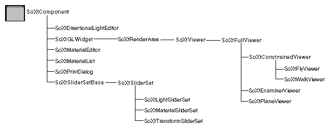
Each component contains a user interface with such things as buttons, menus, and sliders that allow the user to change the scene graph interactively. One example of a component is the material editor, used in Examples 16-2, 16-3, and 16-4. With this editor, the user can customize objects shown in the Inventor window by interactively changing values for ambient, diffuse, specular, transparent, emissive, and shininess elements and immediately see the effects of those changes. Another example is the examiner viewer, which enables the user to move the camera through the scene, providing real-time changes in how the scene is viewed. Figure 18.1, “ Component Classes ” shows the component class tree.
An SoXtComponent( C++ ) is an Inventor C++ wrapper around a Motif-compliant widget. This means that you can layer components in a window with other Motif widgets using standard layout schemes such as bulletin boards, form widgets, and row/column widgets. The material editor itself is an SoXtComponent( C++ ) made up of other components and Motif-style widgets. (Its color sliders are derived from SoXtComponent( C++ ), and the radio buttons, toggle buttons, and menu are Motif-style widgets.) You can pass in a widget name to each component, which can then be used in resource files as the Motif name of the widget.
Components fall into two general classes, viewers and editors, depending on which part of the scene graph they affect. Viewers affect the camera node in the scene, and editors affect other nodes and fields in the scene, such as SoMaterial( C++ | Java | .NET ) nodes and SoDirectionalLight( C++ | Java | .NET ) nodes.
Follow these general steps to use any component in your program. (Additional considerations for specific components are outlined in the following sections.)
Create the component using its constructor. Pass in the parent widget, the widget name, and whether it should build itself inside the parent widget.
Show or hide the component.
Pass data from the component to the application.
Create the component using its constructor. The constructor has the form:
SoXtComponent(Widget parent = NULL, const char * name = NULL, SbBool buildInsideParent = TRUE, SbBool getMouseInput = TRUE, SbBool getKeyboardInput = TRUE);
For example:
C++
SoXtMaterialEditor *editor = new
         SoXtMaterialEditor(parentWidget);
This step initializes local variables and structures and builds the component. You supply the parent widget you want the component to appear in. If you do not supply a parent widget, or if you pass FALSE for the buildInsideParent parameter, the component is created inside its own shell. An important side effect is that if the component is put in its own window, it can resize itself when necessary. If the component is built into the widget tree, it cannot resize itself. If you do not supply a name, the name is the class name—“SoXtMaterialEditor,” in this case.
If you specify FALSE for the buildInsideParent parameter, the component is built inside its own shell, but it uses the passed parent as part of the widget hierarchy for X resource lookup.
The show() and hide() methods are routines that allow you to manage the component widget. In summary, the show() method is used to make the component visible. The hide() method is used to make the component invisible. However, in Motif-compliant applications, the topmost parent of the widget tree must be realized before its children are displayed. Additionally, only the children that are managed are displayed.
If the Inventor component is a top-level shell widget (that is, no parent widget was passed to the constructor), the show() method causes the component to call XtRealizeWidget() on itself, and XtManageChild() on its children.
If the component is not a top-level shell widget, the show() method causes the component to call XtManageChild() on itself and all its children. These widgets won't be visible, though, until XtRealizeWidget() is called on the top-level widget.
The show() and hide() methods on SoXtComponent( C++ ) do some additional work that the component relies on. When you use a component, be sure to call its show() method, not XtManage() or XtRealize(), and hide(), not XtUnmanage() and XtUnrealize(). For instance:
C++
SoXtRenderArea *ra = new SoXtRenderArea();
ra->show();
Each component also has a series of specialized methods for changing its behavior while the program is running. (See SoXtComponent( C++ ) in the Open Inventor C++ Reference Manual.) These methods include the following:
There are two ways for a component to pass data back to the application:
Use a callback list to inform the application when certain changes occur in the component (see Example 18.2, “ Using a Callback Function ”). Callbacks are useful when you want to affect more than one node (you can attach a component to only one node at a time).
Attach the component to a node (or field) in the scene graph (see Example 18.3, “ Attaching a Material Editor ”). For viewers, this is the only way to pass data back to the application; viewers are attached to an entire scene graph.
Editor components such as the material editor can also use callback functions to pass data back to the application. Example 18.2, “ Using a Callback Function ” illustrates the use of a callback procedure with the material editor.
A list of callback functions and associated data, SoCallbackList( C++ ), is automatically created when a component is constructed. You can add functions to and remove functions from this list and pass a pointer to the callback data.
Some widgets, such as viewers, use lists of callback functions:
Start callbacks—called when interaction starts (for example, on a mouse down event)
Finish callbacks—called when interaction finishes (for example, on a mouse-up event)
The following methods add functions to and remove functions from these callback lists:
addStartCallback(functionName, userData) removeStartCallback(functionName, userData)
addFinishCallback(functionName, userData) removeFinishCallback(functionName, userData)
The material editor invokes its callbacks or updates the nodes it is attached to according to a programmable update frequency. Use the setUpdateFrequency() method to specify this frequency. Choices are as follows:
CONTINUOUS | continuously update the field as the value changes (the default) |
AFTER_ACCEPT | update the field only when the user hits the accept button |
Example 18.2, “ Using a Callback Function ” builds a render area in a window supplied by the application and a material editor in its own window. It uses callbacks for the component to report new values.
Example 18.2. Using a Callback Function
C++
#include <Inventor/SoDB.h>
#include <Inventor/Xt/SoXt.h>
#include <Inventor/Xt/SoXtMaterialEditor.h>
#include <Inventor/Xt/SoXtRenderArea.h>
#include <Inventor/nodes/SoDirectionalLight.h>
#include <Inventor/nodes/SoMaterial.h>
#include <Inventor/nodes/SoPerspectiveCamera.h>
#include <Inventor/nodes/SoSeparator.h>

// This is called by the Material Editor when a value changes
void
myMaterialEditorCB(void *userData, const SoMaterial *newMtl)
{
   SoMaterial *myMtl = (SoMaterial *) userData;

   myMtl->copyFieldValues(newMtl);
}

main(int , char **argv)
{
   // Initialize Inventor and Xt
   Widget myWindow = SoXt::init(argv[0]);

   // Build the render area in the applications main window
   SoXtRenderArea *myRenderArea = new SoXtRenderArea(myWindow);
   myRenderArea->setSize(SbVec2s(200, 200));
   // Build the Material Editor in its own window
   SoXtMaterialEditor *myEditor = new SoXtMaterialEditor;

   // Create a scene graph
   SoSeparator *root = new SoSeparator;
   SoPerspectiveCamera *myCamera = new SoPerspectiveCamera;
   SoMaterial *myMaterial = new SoMaterial;
   root->ref();
   myCamera->position.setValue(0.212482, -0.881014, 2.5);
   myCamera->heightAngle = M_PI/4;
   root->addChild(myCamera);
   root->addChild(new SoDirectionalLight);
   root->addChild(myMaterial);

   // Read the geometry from a file and add to the scene
   SoInput myInput;
   if (!myInput.openFile("dogDish.iv"))
      exit (1);
   SoSeparator *geomObject = SoDB::readAll(&myInput);
   if (geomObject == NULL)
      exit (1);
   root->addChild(geomObject);

   // Add a callback for when the material changes
   myEditor->addMaterialChangedCallback(
         myMaterialEditorCB, myMaterial);

   // Set the scene graph
   myRenderArea->setSceneGraph(root);

   // Show the main window and the Material Editor
   myRenderArea->setTitle("Editor Callback");
   myRenderArea->show();
   SoXt::show(myWindow);
   myEditor->show();

   // Loop forever
   SoXt::mainLoop();
}
One way to affect a scene graph directly is to attach an editor component to a node in the scene graph. Example 18.3, “ Attaching a Material Editor ” shows using the attach() method to attach the material editor to a material node:
C++
myEditor->attach(myMaterial);
The syntax for attach() here is
attach(SoMaterial *material, int index = 0);
material | the node to edit |
index | for multiple-value materials, the index within the node of the material to edit |
In the same way, viewers are “attached” to the scene graph whose camera they edit. For example:
C++
SoXtFlyViewer *spaceShip = new SoXtFlyViewer;
spaceShip->setSceneGraph(root);
See the section called “Viewers” for a detailed description of what happens when a viewer is attached to a scene graph.
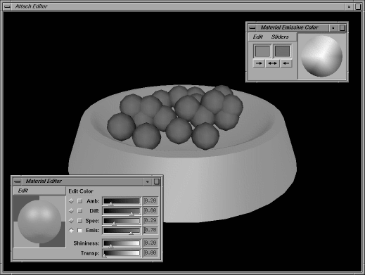
Example 18.3, “ Attaching a Material Editor ” builds a render area in a window supplied by the application and a material editor in its own window. It attaches the editor to the material of an object. Figure 18.2, “ Material Editor and Render Area Created in Separate Windows ” shows the image created by this example.
Example 18.3. Attaching a Material Editor
C++
#include <Inventor/SoDB.h>
#include <Inventor/Xt/SoXt.h>
#include <Inventor/Xt/SoXtMaterialEditor.h>
#include <Inventor/Xt/SoXtRenderArea.h>
#include <Inventor/nodes/SoDirectionalLight.h>
#include <Inventor/nodes/SoMaterial.h>
#include <Inventor/nodes/SoPerspectiveCamera.h>
#include <Inventor/nodes/SoSeparator.h>

main(int , char **argv)
{
   // Initialize Inventor and Xt
   Widget myWindow = SoXt::init(argv[0]);
C++
   // Build the render area in the applications main window
   SoXtRenderArea *myRenderArea = new SoXtRenderArea(myWindow);
   myRenderArea->setSize(SbVec2s(200, 200));

   // Build the material editor in its own window
   SoXtMaterialEditor *myEditor = new SoXtMaterialEditor;

   // Create a scene graph
   SoSeparator *root = new SoSeparator;
   SoPerspectiveCamera *myCamera = new SoPerspectiveCamera;
   SoMaterial *myMaterial = new SoMaterial;

   root->ref();
   myCamera->position.setValue(0.212482, -0.881014, 2.5);
   myCamera->heightAngle = M_PI/4;
   root->addChild(myCamera);
   root->addChild(new SoDirectionalLight);
   root->addChild(myMaterial);

   // Read the geometry from a file and add to the scene
   SoInput myInput;
   if (!myInput.openFile("dogDish.iv"))
      exit (1);
   SoSeparator *geomObject = SoDB::readAll(&myInput);
   if (geomObject == NULL)
      exit (1);
   root->addChild(geomObject);

   // Set the scene graph
   myRenderArea->setSceneGraph(root);

   // Attach material editor to the material
   myEditor->attach(myMaterial);

   // Show the application window and the material editor
   myRenderArea->setTitle("Attach Editor");
   myRenderArea->show();
   SoXt::show(myWindow);
   myEditor->show();

   // Loop forever
   SoXt::mainLoop();
}
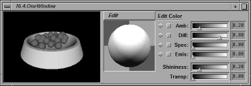
Example 18.4, “ Placing Two Components in the Same Window ” builds a render area and a material editor in a window supplied by the application. It uses a Motif-compliant form widget to lay both components inside the same window. The editor is attached to the material of an object. Figure 18.3, “ Using the Material Editor Component to Edit a Scene ” shows how this example initially looks on the screen.
Example 18.4. Placing Two Components in the Same Window
C++
#include <Xm/Form.h>
#include <Inventor/SoDB.h>
#include <Inventor/Xt/SoXt.h>
#include <Inventor/Xt/SoXtMaterialEditor.h>
#include <Inventor/Xt/SoXtRenderArea.h>
#include <Inventor/nodes/SoDirectionalLight.h>
#include <Inventor/nodes/SoMaterial.h>
#include <Inventor/nodes/SoPerspectiveCamera.h>
#include <Inventor/nodes/SoSeparator.h>

main(int , char **argv)
{
   // Initialize Inventor and Xt
   Widget myWindow = SoXt::init(argv[0]);
   // Build the form to hold both components
   Widget myForm = XtCreateWidget("Form",
            xmFormWidgetClass, myWindow, NULL, 0);

   // Build the render area and Material Editor
   SoXtRenderArea *myRenderArea = new SoXtRenderArea(myForm);
   myRenderArea->setSize(SbVec2s(200, 200));
   SoXtMaterialEditor *myEditor =
            new SoXtMaterialEditor(myForm);

   // Lay out the components within the form
   Arg args[8];
   XtSetArg(args[0], XmNtopAttachment, XmATTACH_FORM);
   XtSetArg(args[1], XmNbottomAttachment, XmATTACH_FORM);
   XtSetArg(args[2], XmNleftAttachment, XmATTACH_FORM);
   XtSetArg(args[3], XmNrightAttachment, XmATTACH_POSITION);
   XtSetArg(args[4], XmNrightPosition, 40);
   XtSetValues(myRenderArea->getWidget(), args, 5);
   XtSetArg(args[2], XmNrightAttachment, XmATTACH_FORM);
   XtSetArg(args[3], XmNleftAttachment, XmATTACH_POSITION);
   XtSetArg(args[4], XmNleftPosition, 41);
   XtSetValues(myEditor->getWidget(), args, 5);

   // Create a scene graph
   SoSeparator *root = new SoSeparator;
   SoPerspectiveCamera *myCamera = new SoPerspectiveCamera;
   SoMaterial *myMaterial = new SoMaterial;


   root->ref();
   myCamera->position.setValue(0.212482, -0.881014, 2.5);
   myCamera->heightAngle = M_PI/4;
C++
   root->addChild(myCamera);
   root->addChild(new SoDirectionalLight);
   root->addChild(myMaterial);

   // Read the geometry from a file and add to the scene
   SoInput myInput;
   if (!myInput.openFile("dogDish.iv"))
      exit (1);
   SoSeparator *geomObject = SoDB::readAll(&myInput);
   if (geomObject == NULL)
      exit (1);
   root->addChild(geomObject);

   // Make the scene graph visible
   myRenderArea->setSceneGraph(root);

   // Attach the material editor to the material in the scene
   myEditor->attach(myMaterial);

   // Show the main window
   myRenderArea->show();
   myEditor->show();
   SoXt::show(myForm); // this calls XtManageChild
   SoXt::show(myWindow); // this calls XtRealizeWidget

   // Loop forever
   SoXt::mainLoop();
}
Viewers, such as the examiner viewer and the fly viewer, change the camera position and thus affect how a scene is viewed. The examiner viewer uses a virtual trackball to rotate the scene graph around a point of interest. With the fly viewer, mouse movements have the effect of tilting the viewer's head up, down, to the left, and to the right, as well as moving in the direction the viewer is facing.
All viewers have the following elements built into them:
A render area in which the scene is being displayed
Thumbwheel and slider trim at the sides, which function differently for each viewer
A pop-up menu controlled by the right mouse button
Viewer icons in the upper right corner that are shortcuts for some of the pop-up menu operations
Optional application icons in the upper left corner
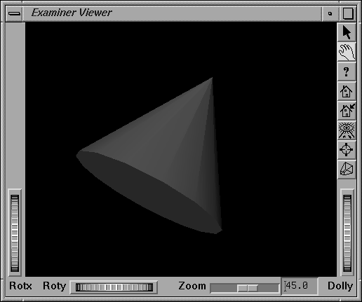
Figure 18.4, “ Examiner Viewer ” shows an example of the examiner viewer.
When you construct a viewer, you can specify whether the viewer is a browser viewer (BROWSER; the default) or an editor viewer (EDITOR). If the browser creates a camera node (see the following section), this camera node is removed from the scene graph when the viewer is detached. If an editor viewer creates a camera node, the camera node is retained when the viewer is detached.
The constructor for each viewer takes an additional parameter that specifies what to build. By default, the decoration and pop-up menu are created. For example, the constructor for the examiner viewer is as follows:
SoXtExaminerViewer(Widget parent = NULL, const char * name = NULL, SbBool buildInsideParent = TRUE, SoXtFullViewer::BuildFlag buildFlag = BUILD_ALL, SoXtViewer::Type type = BROWSER);
The buildFlag can be one of the following values:
BUILD_NONE | the decoration and pop-up menu are not created |
BUILD_DECORATION | only the decoration is created |
BUILD_POPUP | only the pop-up menu is created |
BUILD_ALL | the decoration and pop-up menu are created |
![[Tip]](../images/tip.jpg) | |
Tip: If the user doesn't need the viewer decoration, you can disable the creation of the decoration at construction time using the buildFlag; this will improve performance. |
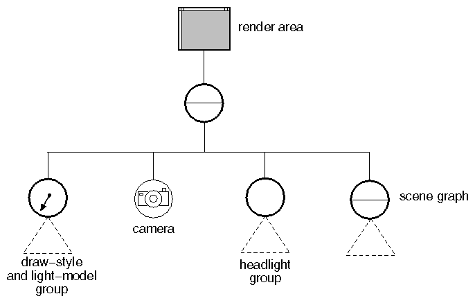
When you call setSceneGraph() for a viewer, several things happen automatically. First, the viewer searches the scene graph for a camera. If it finds one, it uses that camera. If it doesn't find a camera, it adds one. Second, it adds headlight, draw-style, and lighting-model nodes to the scene graph. (The following paragraphs describe these steps in detail.)
Call setSceneGraph(NULL) to disconnect the scene graph from the viewer component. If the viewer created a camera and the viewer is a browser, it removes the camera. If the viewer is an editor, it leaves the camera, since the view is saved along with the scene graph. For both types of viewers, the headlight group is removed when the scene graph is removed.
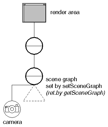
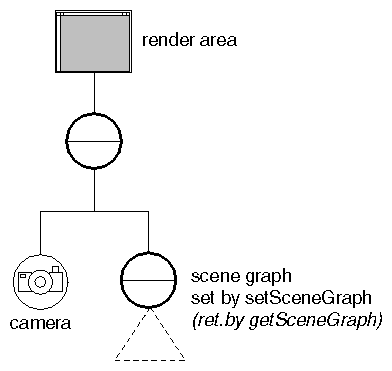
All viewers search from the scene graph root downward for the first camera. If the viewer finds a camera, it uses it. If it doesn't find one, it creates a camera (of class SoPerspectiveCamera( C++ | Java | .NET ) by default). If the viewer is an editor, it inserts the camera under the scene graph root, as shown in Figure 18.5, “ Inserting a Camera for an Editor Viewer ”. When you save the scene graph, this new camera is saved with it. If the viewer is a browser, it inserts the camera above the scene graph, as shown in Figure 18.6, “ Inserting a Camera for a Browser Viewer ”. This camera is not saved with the scene graph and is removed when the viewer is detached.
Viewer components by default also add a directional light source to the scene. The viewer continuously changes the position of this light so that it tracks the camera and functions as a headlight shining on the camera's field of view. This headlight group is added just after the camera in the scene graph. To write the scene graph to a file without the headlight, you can either detach the viewer or turn off the headlight (see the setHeadlight() method for SoXtViewer( C++ )in the Open Inventor C++ Reference Manual).
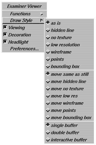
All viewers include a pop-up menu that allows you to change the draw-style of the entire scene. Sometimes, when the viewer changes the draw-style, it also changes the lighting model (for example, wireframe draw-style uses base-color lighting). When a viewer is attached, it inserts draw-style and lighting-model nodes above the scene graph, as shown in Figure 18.7, “ Inserting Drawing Style and Lighting Model Nodes ”. The following list describes the choices for draw-style and the accompanying changes in lighting model:
VIEW_AS_IS | ignores viewer's draw-style and lighting-model nodes (the default). |
VIEW_HIDDEN_LINE | forces all shapes to be wireframe and changes lighting to BASE_COLOR. This style displays only the edges of front-facing polygons (back lines are hidden). |
VIEW_NO_TEXTURE | forces all shapes to be rendered without textures. |
VIEW_LOW_COMPLEXITY | forces all shapes to be rendered with a low complexity and no textures. |
VIEW_LINE | forces all shapes to be wireframe and changes the lighting model to BASE_COLOR. |
VIEW_POINT | forces all shapes to be points and changes the lighting model to BASE_COLOR and the point size to 3.0. |
VIEW_BBOX | forces all shapes to be rendered as bounding boxes. |
The draw-styles above can affect the scene while the camera is still, or while the user is interactively moving the camera. When the draw-style is set, you can choose between two settings, STILL and INTERACTIVE, to show which state should be affected. Use the setDrawStyle() method for SoXtViewer( C++ ) to specify the draw style and draw type:
setDrawStyle(SoXtViewer::DrawType type, SoXtViewer::DrawStyle style)
For example:
C++
setDrawStyle(SoXtViewer::INTERACTIVE,
	SoXtViewer::VIEW_LINE);
The viewer pop-up menu, shown in Figure 18.8, “ Viewer Pop-up Menu ”, lists the draw-style choices for STILL, the choices for INTERACTIVE, and the choices for buffering type.
Use the setBufferingType() method for SoXtViewer( C++ ) to specify whether the viewer should use single buffering, double buffering, or a combination. The default buffering type is double buffering. Double buffering provides smoother redraws, but offers fewer colors. Buffering types are as follows:
SoXtViewer::BUFFER_SINGLE | |
SoXtViewer::BUFFER_DOUBLE | |
SoXtViewer::BUFFER_INTERACTIVE | uses double buffering only when the user is doing interactive work; otherwise, uses single buffering |
Other useful methods for SoXtViewer( C++ ) include the following:
See SoXtViewer( C++ ) in the Open Inventor C++ Reference Manual for further details.
The SoXtFullViewer( C++ ) class, derived from SoXtViewer( C++ ), is the abstract base class for all viewers that include decoration around the render area. This decoration is made up of thumbwheels, sliders, and push buttons. The setDecoration() method allows you to show or hide the component trims. The setPopupMenuEnabled() method allows you to enable or disable the viewer pop-up menu.
You can add optional application icons to the upper left corner of the component. Use the following methods to add these icons:
adds a push button for the application to the end of the button list | |
places a push button at the specified index in the button list | |
removes a push button from the button list |
See SoXtFullViewer( C++ ) in the Open Inventor C++ Reference Manual for further details.
Example 18.5, “ Using a Browser Examiner Viewer ” creates a simple scene graph with a material and a dish. It then creates a browser examiner viewer and attaches it to the scene graph. The camera and light in the scene are automatically created by the viewer.
Example 18.5. Using a Browser Examiner Viewer
C++
#include <Inventor/SoDB.h>
#include <Inventor/Xt/SoXt.h>
#include <Inventor/Xt/viewers/SoXtExaminerViewer.h>
#include <Inventor/nodes/SoSeparator.h>

main(int , char **argv)
{
   // Initialize Inventor and Xt
   Widget myWindow = SoXt::init(argv[0]);

   // Build the viewer in the application's main window
   SoXtExaminerViewer *myViewer =
      new SoXtExaminerViewer(myWindow);

   // Read the geometry from a file and add to the scene
   SoInput myInput;
   if (!myInput.openFile("dogDish.iv"))
      exit (1);
   SoSeparator *geomObject = SoDB::readAll(&myInput);
   if (geomObject == NULL)
      exit (1);

   // Attach the viewer to the scene graph
   myViewer->setSceneGraph(geomObject);

   // Show the main window
   myViewer->show();
   SoXt::show(myWindow);

   // Loop forever
   SoXt::mainLoop();
}
This section describes the convenience routines provided by Inventor for exchanging Inventor data between applications. Inventor's copy and paste methods conform to the X Consortium's Inter-Client Communication Conventions Manual (ICCCM), July 1989, which presents guidelines on how processes communicate with each other when exchanging data.
Inventor currently supports two data types, Inventor and string. If you need to copy and paste additional data types, or if you need more control over copy and paste functions than is provided by Inventor's convenience routines, you can use the Motif or Xt data-exchange routines directly. For more information, see the X Toolkit Intrinsics Programming Manual by Adrian Nye and Tim O'Reilly (Sebastopol, Ca.: O'Reilly & Associates, 1990).
The SoXtClipboard( C++ ) class handles the details of exchanging data according to the ICCCM guidelines. This class includes a constructor, as well as copy() and paste() methods.
The constructor for SoXtClipboard( C++ ) has the following syntax:
SoXtClipboard( C++ )(Widget w, Atom selectionAtom = _XA_CLIPBOARD_);
The clipboard is associated with a particular widget, such as a render area widget or a top-level widget. For example, you could pass in
C++
renderArea->getWidget()
as the first parameter of this constructor.
The X Toolkit supports several types of selections (primary, secondary, and clipboard; these are also referred to as selection atoms). By default, Inventor supports the clipboard selection (_XA_CLIPBOARD_). If you need to perform data transfers from the primary or secondary selections, you can specify the selection type in the constructor for SoXtClipboard( C++ ). In most cases, however, you use the default selection type.
Use one of Inventor's three copy() methods to copy data onto the SoXtClipboard( C++ ). You can specify a node, a path, or a path list to copy:
copy(SoNode *node, Time eventTime);
copy(SoPath *path, Time eventTime);
copy(SoPathList &pathList, Time eventTime);
The copy() and paste() methods require an event time, which is the time stamp from the user event that triggered the copy or paste request. This event could be a keyboard press event or a menu pick event, for example, and is used by the X server to synchronize copy and paste requests. Behind the scenes, the data is copied into a bytestream and made available to any X client that requests it.
The paste() method also requires a callback function that is invoked with the paste data. The paste data is always a path list, regardless of what was copied originally:
paste(Time eventTime, SoXtClipboardPasteCB pasteDoneFunc, void userData = NULL);
The paste() method requests data from the X server and calls the pasteDoneFunc when the data is ready. A paste is asynchronous. It simply makes a request to the X server for data to paste and then returns. When the data is delivered, the pasteDoneFunc is called and passed the user data along with a list of paths that were pasted. If no data is delivered, the pasteDoneFunc is never called. It is up to the application to delete the path list for the paste data when the application is finished with it.
