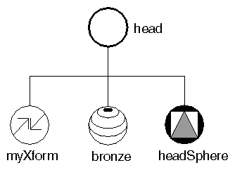
Suppose you want to combine the transform node, the material node, and the sphere node created earlier into a single group, the “head” group for a robot object. First, create the SoGroup( C++ | Java | .NET ). Then use the addChild() method for each child node, as follows:
C++
SoGroup *head = new SoGroup;

head->addChild(myXform);
head->addChild(bronze);
head->addChild(headSphere);
.NET
SoGroup head = new SoGroup();

head.AddChild(myXform);
head.AddChild(bronze);
head.AddChild(headSphere);
Java
SoGroup head = new SoGroup();

head.addChild(myXform);
head.addChild(bronze);
head.addChild(headSphere);
Figure 3.5, “ Simple Group ” shows a diagram of this group. All scene graph diagrams use the icons shown in Figure 1, “ Scene Graph Symbols ”. By convention, all figures show the first child in the group on the left, and ordering of children is from left to right.
The addChild() method adds the specified node to the end of the list of children in the group, as shown in the preceding code. Each child added to the group has an associated index. The first child in a group has an index of 0, the second child in a group has an index of 1, and so on.
C++
void insertChild(SoNode *child, int newChildIndex);
.NET
void InsertChild(SoNode child, int newChildIndex);
Java
void insertChild(SoNode child, int newChildIndex);
inserts a child node into a group at the location specified by newChildIndex. For example,
C++
SoDrawStyle *wireStyle;

wireStyle = new SoDrawStyle;
wireStyle->style = SoDrawStyle::LINES;
// Insert as child 1 (the node right after the first child,
// which is child 0.
body->insertChild(wireStyle, 1);
.NET
SoDrawStyle wireStyle = new SoDrawStyle();

wireStyle.style.Value = SoDrawStyle.Styles.LINES;
// Insert as child 1 (the node right after the first child,
// which is child 0.
body.InsertChild(wireStyle, 1);
Java
SoDrawStyle wireStyle = new SoDrawStyle();

wireStyle.style.setValue(SoDrawStyle.Styles.LINES);
// Insert as child 1 (the node right after the first child,
// which is child 0.
body.insertChild(wireStyle, 1);
inserts a wireframe drawing-style node as the second child of the body group.
Other group methods allow you to find out how many children are in a group, to find the index of a particular child, to access the child with a given index, and to remove children.
Each node class has its own way of responding to a given database action. For this discussion, assume you are dealing only with the GL rendering action (here called simply rendering).
If the node to be rendered is a groupnode, it invokes the rendering action on each of its children in order, typically from left to right in the scene graph.
Each child node in turn executes its own rendering method, which then affects the traversal state in some way (see Chapter 8, Applying Actions). If the child node is a property node, it modifies one or more elements in the traversal state, such as the value used for diffuse color, the value used for scaling an object, or the value used for line width. Most property nodes simply replace the values for an element in the traversal state. (A bronze material node replaces values in the material element with its own new values.) Geometric transformations are exceptions because they combine with each other to make composite transformations.
If the child node is a shape node, it draws itself using the current traversal state.
During rendering, the scene graph is traversed, starting from the root node, from left to right and from top to bottom. Nodes to the right (and down) in the graph inherit the traversal state set by nodes to the left (and above).
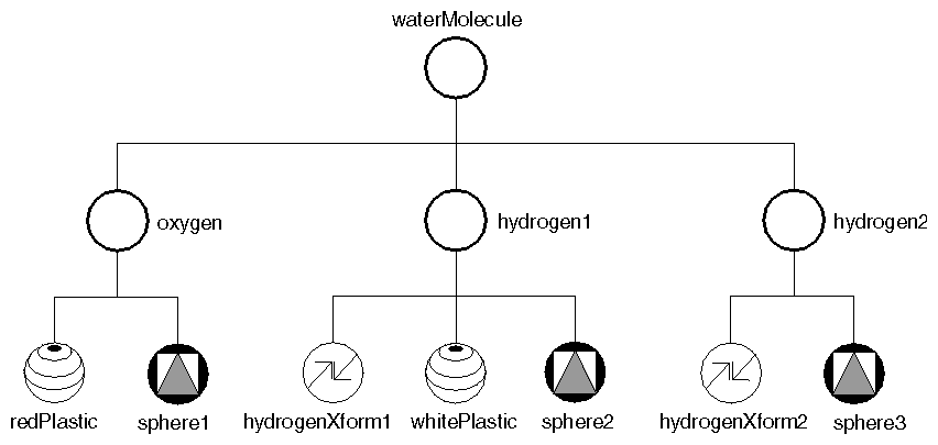
Figure 3.6, “ Combining Groups ” shows how nodes inherit state. When the waterMolecule node is rendered, it visits its first child, oxygen. The oxygen group then visits each of its children, as follows:
The material node (redPlastic) changes the material element to a shiny red surface.
The sphere node (sphere1) causes a sphere to be rendered using the current traversal state. A shiny red sphere is drawn at the origin.
The graph traversal continues to the next group on the right, hydrogen1, which in turn visits each of its children in order from left to right:
The transform node (hydrogenXform1) modifies the transformation matrix (let's say it scales by a factor of 0.75 in x, y, and z). It also modifies the transformation matrix by adding a translation of 0.0, -1.2, 0.0 (in x, y, and z).
The material node (whitePlastic) changes the material element to a shiny white surface.
The sphere node (sphere2) causes another sphere to be rendered using the modified traversal state. This sphere is white. Additionally, sphere2 appears in a new location and is scaled down in size, the result of the SoTransform( C++ | Java | .NET ) node in its group.
Next, the hydrogen2 group visits its children, from left to right:
The transform node (hydrogenXform2) modifies the transformation matrix, translating in the +x and +y directions.
The sphere node (sphere3) causes the third sphere to be rendered using the modified traversal state. This sphere is still white and scaled by 0.75 because it inherits these attributes from the hydrogen1 group.
Example 3.1, “ Molecule ” shows the code to create this molecule.
Example 3.1. Molecule
C++
// Construct all parts
SoGroup *waterMolecule = new SoGroup;      // water molecule

SoGroup *oxygen = new SoGroup;             // oxygen atom
SoMaterial *redPlastic = new SoMaterial;
SoSphere *sphere1 = new SoSphere;

SoGroup *hydrogen1 = new SoGroup;          // hydrogen atoms
SoGroup *hydrogen2 = new SoGroup;
SoTransform *hydrogenXform1 = new SoTransform;
SoTransform *hydrogenXform2 = new SoTransform;
SoMaterial *whitePlastic = new SoMaterial;
SoSphere *sphere2 = new SoSphere;
SoSphere *sphere3 = new SoSphere;

// Set all field values for the oxygen atom
redPlastic->ambientColor.setValue(1.0, 0.0, 0.0);
redPlastic->diffuseColor.setValue(1.0, 0.0, 0.0);
redPlastic->specularColor.setValue(0.5, 0.5, 0.5);
redPlastic->shininess = 0.5;

// Set all field values for the hydrogen atoms
hydrogenXform1->scaleFactor.setValue(0.75, 0.75, 0.75);
hydrogenXform1->translation.setValue(0.0, -1.2, 0.0);
hydrogenXform2->translation.setValue(1.1852, 1.3877, 0.0);
whitePlastic->ambientColor.setValue(1.0, 1.0, 1.0);
whitePlastic->diffuseColor.setValue(1.0, 1.0, 1.0);
whitePlastic->specularColor.setValue(0.5, 0.5, 0.5);
whitePlastic->shininess = 0.5;

// Create a hierarchy
waterMolecule->addChild(oxygen);
waterMolecule->addChild(hydrogen1);
waterMolecule->addChild(hydrogen2);

oxygen->addChild(redPlastic);
oxygen->addChild(sphere1);
hydrogen1->addChild(hydrogenXform1);
hydrogen1->addChild(whitePlastic);
hydrogen1->addChild(sphere2);
hydrogen2->addChild(hydrogenXform2);
hydrogen2->addChild(sphere3);
.NET
// Construct all parts
SoGroup waterMolecule = new SoGroup();  // water molecule

SoGroup oxygen = new SoGroup();         // oxygen atom
SoMaterial redPlastic = new SoMaterial();
SoSphere sphere1 = new SoSphere();

SoGroup hydrogen1 = new SoGroup();      // hydrogen atoms
SoGroup hydrogen2 = new SoGroup();
SoTransform hydrogenXform1 = new SoTransform();
SoTransform hydrogenXform2 = new SoTransform();
SoMaterial whitePlastic = new SoMaterial();
SoSphere sphere2 = new SoSphere();
SoSphere sphere3 = new SoSphere();

// Set all field values for the oxygen atom
redPlastic.ambientColor.SetValue(1.0f, 0.0f, 0.0f);
redPlastic.diffuseColor.SetValue(1.0f, 0.0f, 0.0f);
redPlastic.specularColor.SetValue(0.5f, 0.5f, 0.5f);
redPlastic.shininess.SetValue(0.5f);

// Set all field values for the hydrogen atoms
hydrogenXform1.scaleFactor.SetValue(0.75f, 0.75f, 0.75f);
hydrogenXform1.translation.SetValue(0.0f, -1.2f, 0.0f);
hydrogenXform2.translation.SetValue(1.1852f, 1.3877f, 0.0f);
whitePlastic.ambientColor.SetValue(1.0f, 1.0f, 1.0f);
whitePlastic.diffuseColor.SetValue(1.0f, 1.0f, 1.0f);
whitePlastic.specularColor.SetValue(0.5f, 0.5f, 0.5f);
whitePlastic.shininess.SetValue(0.5f);

// Create a hierarchy
waterMolecule.AddChild(oxygen);
waterMolecule.AddChild(hydrogen1);
waterMolecule.AddChild(hydrogen2);

oxygen.AddChild(redPlastic);
oxygen.AddChild(sphere1);
hydrogen1.AddChild(hydrogenXform1);
hydrogen1.AddChild(whitePlastic);
hydrogen1.AddChild(sphere2);
hydrogen2.AddChild(hydrogenXform2);
hydrogen2.AddChild(sphere3);
Java
// Construct all parts
SoGroup waterMolecule = new SoGroup();
SoGroup oxygen = new SoGroup();
SoMaterial redPlastic = new SoMaterial();
SoSphere sphere1 = new SoSphere();

SoGroup hydrogen1 = new SoGroup();
SoGroup hydrogen2 = new SoGroup();
SoTransform hydrogenXform1 = new SoTransform();
SoTransform hydrogenXform2 = new SoTransform();
SoMaterial whitePlastic = new SoMaterial();
SoSphere sphere2 = new SoSphere();
SoSphere sphere3 = new SoSphere();

// Set all field values for the oxygen atom
redPlastic.ambientColor.setValue(1.0F,0.0F,0.0F);
redPlastic.diffuseColor.setValue(1.0F,0.0F,0.0F);
redPlastic.specularColor.setValue(0.5F,0.5F,0.5F);
redPlastic.shininess.setValue(0.5F);

// Set all field values for the hydrogen atom
hydrogenXform1.scaleFactor.setValue(0.75F,0.75F,0.75F);
hydrogenXform1.translation.setValue(0.0F,-1.2F,0.0F);
hydrogenXform2.translation.setValue(1.1852F,1.3877F,0.0F);

whitePlastic.ambientColor.setValue(1.0F,1.0F,1.0F);
whitePlastic.diffuseColor.setValue(1.0F,1.0F,1.0F);
whitePlastic.specularColor.setValue(0.5F,0.5F,0.5F);
whitePlastic.shininess.setValue(0.5F);

// Create a hierarchy
waterMolecule.addChild(oxygen);
waterMolecule.addChild(hydrogen1);
waterMolecule.addChild(hydrogen2);

oxygen.addChild(redPlastic);
oxygen.addChild(sphere1);
hydrogen1.addChild(hydrogenXform1);
hydrogen1.addChild(whitePlastic);
hydrogen1.addChild(sphere2);
hydrogen2.addChild(hydrogenXform2);
hydrogen2.addChild(whitePlastic);
hydrogen2.addChild(sphere3);
To isolate the effects of nodes in a group, use an SoSeparator( C++ | Java | .NET ) node, which is a subclass of SoGroup( C++ | Java | .NET ). Before traversing its children, an SoSeparator( C++ | Java | .NET ) saves the current traversal state. When it has finished traversing its children, the SoSeparator( C++ | Java | .NET ) restores the previous traversal state. Nodes within an SoSeparator( C++ | Java | .NET ) thus do not affect anything above or to the right in the graph.
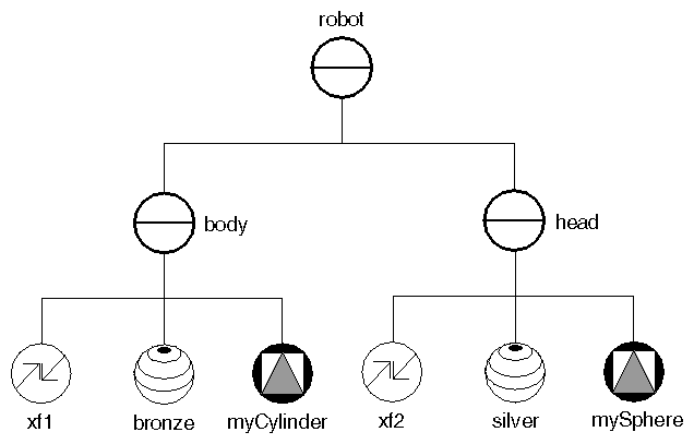
Figure 3.7, “ Separator Groups ”, for example, shows the body and head for a robot. The body group, a separator, contains SoTransform( C++ | Java | .NET ) and SoMaterial( C++ | Java | .NET ) nodes that affect the traversal state used by the cylinder in that group. These values are restored when all children in the body group have been visited, so the head group is unaffected by the body-group nodes. Because the head group is also a separator group, the traversal state is again saved when group traversal begins and restored when group traversal finishes.
Separators are inexpensive to use and help to structure scene graphs. You will probably use them frequently.
![[Tip]](../images/tip.jpg) | |
Tip: The root node of a scene graph should be a separator if you want the state to be reset between successive renderings. |
Code for the robot body and head groups is shown below:
C++
// create body parts
SoTransform *xf1 = new SoTransform;
xf1->translation.setValue(0.0, 3.0, 0.0);

SoMaterial *bronze = new SoMaterial;
bronze->ambientColor.setValue(.33, .22, .27);
bronze->diffuseColor.setValue(.78, .57, .11);
bronze->specularColor.setValue(.99, .94, .81);
bronze->shininess = .28;

SoCylinder *myCylinder = new SoCylinder;
myCylinder->radius = 2.5;
myCylinder->height = 6;

// construct body out of parts
SoSeparator *body = new SoSeparator;
body->addChild(xf1);
body->addChild(bronze);
body->addChild(myCylinder);

// create head parts
SoTransform *xf2 = new SoTransform;
xf2->translation.setValue(0, 7.5, 0);
xf2->scaleFactor.setValue(1.5, 1.5, 1.5);

SoMaterial *silver = new SoMaterial;
silver->ambientColor.setValue(.2, .2, .2);
silver->diffuseColor.setValue(.6, .6, .6);
silver->specularColor.setValue(.5, .5, .5);
silver->shininess = .5;

SoSphere *mySphere = new SoSphere;

// construct head out of parts
SoSeparator *head = new SoSeparator;
head->addChild(xf2);
head->addChild(silver);
head->addChild(mySphere);

// add head and body
SoSeparator *robot = new SoSeparator;
robot->addChild(body);
robot->addChild(head);
.NET
// create body parts
SoTransform bodyTransform = new SoTransform();
bodyTransform.translation.SetValue(0.0f, 3.0f, 0.0f);

SoMaterial bronze = new SoMaterial();
bronze.ambientColor.SetValue(0.33f, 0.22f, 0.27f);
bronze.diffuseColor.SetValue(0.78f, 0.57f, 0.11f);
bronze.specularColor.SetValue(0.99f, 0.94f, 0.81f);
bronze.shininess.SetValue(0.28f);

SoCylinder bodyCylinder = new SoCylinder();
bodyCylinder.radius.Value = 2.5f;
bodyCylinder.height.Value = 6.0f;

// Construct body out of parts
SoSeparator body = new SoSeparator();
body.AddChild(bodyTransform);
body.AddChild(bronze);
body.AddChild(bodyCylinder);

// Head parts
SoTransform headTransform = new SoTransform();
headTransform.translation.SetValue(0.0f, 7.5f, 0.0f);
headTransform.scaleFactor.SetValue(1.5f, 1.5f, 1.5f);

SoMaterial silver = new SoMaterial();
silver.ambientColor.SetValue(0.2f, 0.2f, 0.2f);
silver.diffuseColor.SetValue(0.6f, 0.6f, 0.6f);
silver.specularColor.SetValue(0.5f, 0.5f, 0.5f);
silver.shininess.SetValue(0.5f);

SoSphere headSphere = new SoSphere();

// Construct head
SoSeparator head = new SoSeparator();
head.AddChild(headTransform);
head.AddChild(silver);
head.AddChild(headSphere);

// add head and body
SoSeparator robot = new SoSeparator();
robot.AddChild(body);
robot.AddChild(head);
Java
// create body parts
SoTransform bodyTransform = new SoTransform();
bodyTransform.translation.setValue(0.0f, 3.0f, 0.0f);

SoMaterial bronze = new SoMaterial();
bronze.ambientColor.setValue(0.33f, 0.22f, 0.27f);
bronze.diffuseColor.setValue(0.78f, 0.57f, 0.11f);
bronze.specularColor.setValue(0.99f, 0.94f, 0.81f);
bronze.shininess.setValue(0.28f);

SoCylinder bodyCylinder = new SoCylinder();
bodyCylinder.radius.setValue(2.5f);
bodyCylinder.height.setValue(6.0f);

// Construct body out of parts
SoSeparator body = new SoSeparator();
body.addChild(bodyTransform);
body.addChild(bronze);
body.addChild(bodyCylinder);

// Head parts
SoTransform headTransform = new SoTransform();
headTransform.translation.setValue(0.0f, 7.5f, 0.0f);
headTransform.scaleFactor.setValue(1.5f, 1.5f, 1.5f);

SoMaterial silver = new SoMaterial();
silver.ambientColor.setValue(0.2f, 0.2f, 0.2f);
silver.diffuseColor.setValue(0.6f, 0.6f, 0.6f);
silver.specularColor.setValue(0.5f, 0.5f, 0.5f);
silver.shininess.setValue(0.5f);

SoSphere headSphere = new SoSphere();

// Construct head
SoSeparator head = new SoSeparator();
head.addChild(headTransform);
head.addChild(silver);
head.addChild(headSphere);

// add head and body
SoSeparator robot = new SoSeparator();
robot.addChild(body);
robot.addChild(head);
In addition to SoSeparator( C++ | Java | .NET ), other subclasses of SoGroup( C++ | Java | .NET ) include the following:
SoSelection (see Chapter 10, Handling Events and Selection)
In the robot example, SoSeparator( C++ | Java | .NET ) nodes are used to contain the effects of nodes within a particular group in the scene graph; you do not want the head to inherit the transformation or material attributes from the body group. Conversely, the molecule example uses SoGroup( C++ | Java | .NET ) nodes to accumulate a set of properties to apply to other nodes later in the graph.
An SoSwitch( C++ | Java | .NET ) node is exactly like an SoGroup( C++ | Java | .NET ) except that it visits only one of its children. It contains one field, whichChild, which specifies the index of the child to traverse. For example, the following code specifies to visit node c of switch s:
C++
SoSwitch *s = new SoSwitch;
s->addChild(a);							// this child has an index of 0
s->addChild(b);							// this child has an index of 1
s->addChild(c);							// this child has an index of 2
s->addChild(d);							// this child has an index of 3
s->whichChild = 2;						 // specifies to visit child(c)
.NET
SoSwitch s = new SoSwitch();
s.AddChild(a);							// this child has an index of 0
s.AddChild(b);							// this child has an index of 1
s.AddChild(c);							// this child has an index of 2
s.AddChild(d);							// this child has an index of 3
s.whichChild.Value = 2;				   // specifies to visit child(c)
Java
SoSwitch s = new SoSwitch();
s.addChild(a);              // this child has an index of 0
s.addChild(b);              // this child has an index of 1
s.addChild(c);              // this child has an index of 2
s.addChild(d);              // this child has an index of 3
s.whichChild.setValue(2);        // specifies to visit child(c)
The default setting of whichChild is SO_SWITCH_NONE, which specifies to traverse none of the group's children.
You can use an SoSwitch( C++ | Java | .NET ) node to switch between several different camera nodes for viewing a scene. You can also use an SoSwitch( C++ | Java | .NET ) node for rudimentary animation. By cycling through a series of groups, you can, for example, make the wings on a duck flap up and down or make a robot walk across the screen. SoBlinker( C++ | Java | .NET ), derived from SoSwitch( C++ | Java | .NET ), cycles among its children (see Chapter 15, Engines) and provides some additional controls useful for animation.
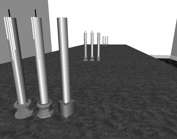
The SoLevelOfDetail node allows you to specify the same object with varying levels of detail. The children of this node are arranged from highest to lowest level of detail. The size of the objects when projected into the viewport determines which child to use. This node is very useful for applications requiring the fastest rendering possible. It has one field:
screenArea (SoMFFloat) | areas on the screen to use for comparison with the bounding box of the level-of-detail group. By default, this value is 0.0, so the first child in the group is traversed. |
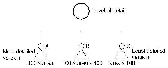
To determine which child to traverse, Inventor computes the 3D bounding box of all children in the level-of-detail group. It projects that bounding box onto the viewport and then computes the area of the screen-aligned rectangle that surrounds the bounding box. This area is then compared to the areas stored in the screenArea field. For example, Figure 3.8, “ Scene Graph with Level-of-Detail Node ” shows a level-of-detail node with three children. Suppose the screenArea field contains the values [400.0, 100.0]. If the bounding-box projection of the group is 390.0 square pixels (that is, less than 400.0 but greater than 100.0), then childB is traversed. If the bounding-box projection of the group is 450.0 pixels (that is, greater than 400.0, then childA is traversed. If the bounding-box projection is less than 100.0, childC is traversed.
TheSoComplexity( C++ | Java | .NET ) node, discussed in Chapter 5, Shapes, Properties, and Binding, also affects the child selection for the level-of-detail node. If complexity is 0.0 or is of type BOUNDING_BOX, the last child inSoLevelOfDetail( C++ | Java | .NET ) is always traversed. If complexity is 1.0, the first child is always used. If the complexity value is greater than 0.0 and less than 0.5, the computed size of the bounding rectangle is scaled down appropriately to use a less detailed representation. If the complexity value is greater than 0.5, the size of the bounding rectangle is scaled up appropriately. If the complexity is 0.5, Inventor uses the computed size of the bounding rectangle as is.
Figure 3.9, “ Different Levels of Detail for an Object ” shows an object modeled with different levels of detail. Each group of candlesticks is arranged with the most detailed model at the left, a medium level of detail in the middle, and the least detailed model at the right. When the candlestick is close to the camera (as in the first group at the left of Figure 3.9, “ Different Levels of Detail for an Object ”), the most detailed model would be used. This model uses a texture on the base of the candlestick and has a detailed candle with a wick. When the object is farthest away, the least detailed model can be used since the details are not visible anyway. When the object is mid-range (the center group of Figure 3.9, “ Different Levels of Detail for an Object ”), the middle model would be used.
