A node is the fundamental element of a scene graph. It contains data and methods that define some specific 3D shape, property, or grouping. When a node is created, it is automatically inserted into the database as a root node. Usually, you connect the node to other nodes in the database to construct a hierarchy.
Nodes are divided into three basic categories:
These categories are not strict and are used only to help you learn about Inventor classes.
Use the new operator to create nodes. For example:
C++
SoSphere *headSphere = new SoSphere;
.NET
SoSphere headSphere = new SoSphere();
Java
SoSphere headSphere = new SoSphere();
Do not allocate nodes in arrays. (See the section called “How Nodes Are Deleted”)
![[Note]](../images/note.jpg) | |
Note: Although you create nodes using the new operator, you cannot delete them using delete. See the section called “How Nodes Are Deleted” for a description of how and when nodes are deleted in Inventor. An understanding of reference counting is vital to your use of Inventor, since you must be aware of the conditions under which a node is automatically deleted. |
Each node is composed of a set of data elements, known as fields, that describe the parameters of the node. For example, a point light-source node (of class SoPointLight( C++ | Java | .NET )) contains four fields: intensity, color, location, and on. The intensity field contains a value from 0.0 (no illumination) to 1.0 (maximum illumination). The color field specifies a Red/Green/Blue illumination color for the light source. The location field specifies the position of the light. The on field specifies whether the light is on.
Inventor defines a number of field types. Each field type has unique methods to get and set its values. Within each node, the fields are named according to their usage. For example, here are a few nodes and their fields:
Node | Fields |
point | |
vector | |
ambientColor diffuseColor specularColor emissiveColor shininess transparency | |
viewportMapping position orientation aspectRatio nearDistance farDistance focalDistance heightAngle |
Note that fields that contain multiple values, such as the point field in SoCoordinate3( C++ | Java | .NET ), have singular names.
Each node implements its own action behavior. When you want to perform a particular action on a scene, you create an instance of the action class (for example, SoGLRenderAction( C++ | Java | .NET ) or SoGetBoundingBoxAction( C++ | Java | .NET )) and then apply it to the root node of the scene graph. For each action, the database manages a traversal state, which is a collection of elements or parameters in the action at a given time. Typically, executing an action involves traversing the graph from top to bottom and left to right. During this traversal, nodes can modify the traversal state, depending on their particular behavior for that action.
This chapter focuses on the OpenGL rendering action, since one of the primary reasons for constructing a 3D database is to view and manipulate
objects. The rendering traversal state consists of a set of elements, each of which can be altered by a given class of nodes. When a rendering action is applied, each element is used and interpreted in a specified manner. A few of the elements in the traversal state include the following:
Current geometric transformation
Current material components
Current lighting model
Current drawing style
Current text font
Current coordinates
Current normals
Current lights
Current viewing specification
An SoMaterial( C++ | Java | .NET ) node, for example, sets the current values in the various material elements of the traversal state. An SoDrawStyle( C++ | Java | .NET ) node sets the current value in the drawing-style element of the traversal state. Shape nodes, such as SoSphere( C++ | Java | .NET ), are especially important in rendering traversal, since they cause their shape to be drawn, using the current values in the traversal state.
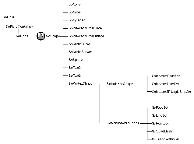
Shape nodes represent 3D geometric objects. They are unique because they describe physical matter that is affected by property and group nodes, and during a rendering action, they actually cause their shape to be drawn on the screen. Classes of shape nodes include SoSphere( C++ | Java | .NET ), SoIndexedFaceSet( C++ | Java | .NET ), and SoText3( C++ | Java | .NET ). Figure 3.2, “ Shape-Node Classes ” shows the portion of the class tree that contains the shape-node classes.
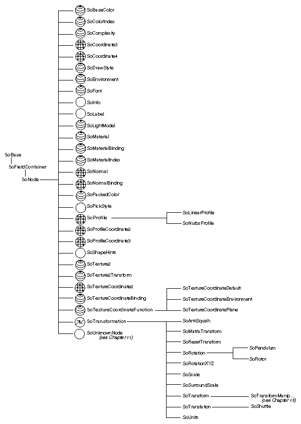
Property nodes represent appearance and qualitative characteristics of the scene, such as surface material, drawing style, or geometric transformation. Figure 3.3, “ Property-Node Classes ” shows the portion of the class tree that contains the property-node classes. Since property nodes fall naturally into several subgroupings, the scene graph diagrams use three different icons for property nodes:
The transform icon is used for nodes that perform transformations, such as SoTransform( C++ | Java | .NET ), SoRotation( C++ | Java | .NET ), SoScale( C++ | Java | .NET ), SoTranslation( C++ | Java | .NET ), SoRotationXYZ( C++ | Java | .NET ), and SoResetTransform( C++ | Java | .NET ). These nodes are all derived from SoTransformation( C++ | Java | .NET ).
The appearance icon is used forodes that modify an object's appearance, such as SoMaterial( C++ | Java | .NET ), SoMaterialBinding( C++ | Java | .NET ), SoBaseColor( C++ | Java | .NET ), SoComplexity( C++ | Java | .NET ), SoDrawStyle( C++ | Java | .NET ), SoLightModel( C++ | Java | .NET ), and SoFont( C++ | Java | .NET ).
The metrics icon is used for nodes that contain coordinate, normal, and other geometric information, such as SoCoordinate3( C++ | Java | .NET ), SoCoordinate4( C++ | Java | .NET ), SoProfileCoordinate2( C++ | Java | .NET ), SoProfileCoordinate3( C++ | Java | .NET ), SoNormal( C++ | Java | .NET ), and SoNormalBinding( C++ | Java | .NET ).
In general, a property node replaces the values in a corresponding element of the traversal state with its own new values. Geometric transformations are one exception to this rule. They concatenate with the current transformation.
Let's take the material node as an example. This node represents the surface and spectral (color) properties of an object. To create a bronze material, first create the material node and then set the field values appropriately:
C++
SoMaterial *bronze = new SoMaterial;

// set field values
bronze->ambientColor.setValue(.33, .22, .27);
bronze->diffuseColor.setValue(.78, .57, .11);
bronze->specularColor.setValue(.99, .94, .81);
bronze->shininess = .28;
.NET
SoMaterial bronze = new SoMaterial();

// set field values
bronze.ambientColor.SetValue(.33f, .22f, .27f);
bronze.diffuseColor.SetValue(.78f, .57f, .11f);
bronze.specularColor.SetValue(.99f, .94f, .81f);
bronze.shininess.SetValue(.28f);
Java
SoMaterial bronze = new SoMaterial();

// set field values
bronze.ambientColor.setValue(.33f, .22f, .27f);
bronze.diffuseColor.setValue(.78f, .57f, .11f);
bronze.specularColor.setValue(.99f, .94f, .81f);
bronze.shininess.setValue(.28f);
If you do not explicitly set the field values for a particular node, Inventor uses the default values for those fields (see the Open Inventor C++ Reference Manual for individual nodes). For example, in the preceding example, transparency remains 0.0.
SoTransform( C++ | Java | .NET ) nodes, which produce geometric transformations, include fields for scaling, rotating, and translating. The following code defines a transform node that translates -1 in the y direction:
C++
SoTransform *myXform = new SoTransform;

// set field value
myXform->translation.setValue(0.0, -1.0, 0.0);
.NET
SoTransform myXform = new SoTransform();

// set field value
myXform.translation.SetValue(0f, -1f, 0f);
Java
SoTransform myXform = new SoTransform();

// set field value
myXform.translation.setValue(0f, -1f, 0f);
In order for this translation to take effect, it must be inserted appropriately into a scene graph (that is, before the shape node to translate).
A group node is a container for collecting child objects. Groups collect property, shape, and other group nodes into graphs. Figure 3.4, “ Group-Node Classes ” shows the portion of the class tree that contains the group-node classes. There are a variety of different group-node classes, each with a specialized grouping characteristic.
When a group node is created, it has no children. The base class for all group nodes isSoGroup( C++ | Java | .NET ), and all nodes derived from it have an addChild() method.


