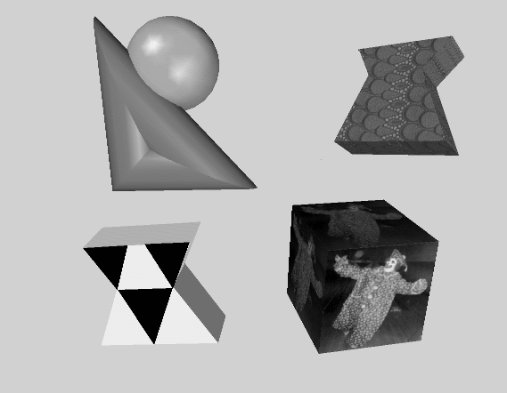
Using textures, you can create a table with a wood grain, an orange with a dimpled, shiny surface, and a field of grass. To do so, first create wood, orange peel, and grass textures and then apply the textures to the various shape objects. Figure 7.1, “ Texture Mapping ” contrasts two sets of objects: the objects on the right use texture mapping, and the objects on the left do not use textures.
A texture map is a 2D image that is applied to a surface of a geometric object. It is an array of pixel information that is read from a file or from memory. Its coordinates are normalized to range from 0.0 to 1.0 in both the s (horizontal) and t (vertical) directions. If the texels in the texture image do not correspond exactly to pixels on the screen, Open Inventor uses a filtering process to cover the polygon properly.
A 3D texture map is similar to a 2D texture map, but with three dimensions. This is a 3D array of texel information that is read from files or from memory. Its coordinates are normalized to range from 0.0 to 1.0 in all three directions: s (horizontal), t (vertical), and r (depth).
Cube map textures are a set of six two-dimensional texture images mapped onto the six faces of a cube centered at the origin. The texture coordinates (s, t, r) are used as a direction vector pointing from the origin. The greatest coordinate is used to select the face and the two others to select a texel from that face. Cube maps are well suited for mapping a reflection of the environment onto an object. (This is also possible using sphere mapping (SoTextureCoordinateEnvironment( C++ | Java | .NET ) ), but only with a specially distorted image.)
This section describes use of the following node classes:
specifies a 2D texture map to be used and associated parameters for texture mapping. | |
explicitly defines the set of 2D texture coordinates to be used by subsequent vertex shapes. | |
specifies how the current texture coordinates are to be bound to subsequent shape nodes. | |
SoTextureCoordinateEnvironment( C++ | Java | .NET ) allow you to use a function to map from spatial coordinates to texture coordinates. | |
turns off any previous texture-coordinate function so that all following shapes use their default texture coordinates. | |
defines a 2D transformation for the texture map. |
The SoComplexity( C++ | Java | .NET ) node has a textureQuality field that relates to texture mapping as well. It allows you to specify a value between 0.0 and 1.0, with 0.0 for the fastest rendering and 1.0 for the finest texturing. (In general, there is a trade-off between speed and the quality of texturing.) The default value for this field is 0.5.
Although you can affect how a texture is applied to an object in many ways, the simplest way to use textures is to use the default values. If you use textures, you need only an SoTexture2( C++ | Java | .NET ) node (for the texture) and a shape node (the target object). Example 7.1, “ Using the Default Texture Values ”, which displays a textured cube, illustrates this method. See Section 7.3, “Texture Nodes” for a detailed description of the SoTexture2( C++ | Java | .NET ) node and its defaults.
Example 7.1. Using the Default Texture Values
C++
#include <Inventor/Xt/SoXt.h>
#include <Inventor/Xt/viewers/SoXtExaminerViewer.h>
#include <Inventor/nodes/SoCube.h>
#include <Inventor/nodes/SoSeparator.h>
#include <Inventor/nodes/SoTexture2.h>

main(int , char **argv)
{
   Widget myWindow = SoXt::init(argv[0]);
   if(myWindow == NULL) exit(1);

   SoSeparator *root = new SoSeparator;
   root->ref();

   // Choose a texture
   SoTexture2 *rock = new SoTexture2;
   root->addChild(rock);
   rock->filename.setValue("brick.1.rgb");

   // Make a cube
   root->addChild(new SoCube);

   SoXtExaminerViewer *myViewer =
            new SoXtExaminerViewer(myWindow);
   myViewer->setSceneGraph(root);
   myViewer->setTitle("Default Texture Coords");
   myViewer->show();

   SoXt::show(myWindow);
   SoXt::mainLoop();
}
.NET
using System.Windows.Forms;

using OIV.Inventor.Nodes;
using OIV.Inventor.Win.Viewers;

namespace _07_1_BasicTexture
{
  public partial class MainForm : Form
  {
    SoWinExaminerViewer myViewer;

    public MainForm()
    {
      InitializeComponent();
      CreateSample();
    }

    public void CreateSample()
    {
      SoSeparator root = new SoSeparator();

      // Choose a texture
      SoTexture2 rock = new SoTexture2();
      root.AddChild(rock);
      rock.filename.Value = "../../../../../data/brick.1.png";

      // Make a cube
      root.AddChild(new SoCube());

      myViewer = new SoWinExaminerViewer(this, "", true,
          SoWinFullViewer.BuildFlags.BUILD_ALL, SoWinViewer.Types.BROWSER);
      myViewer.SetSceneGraph(root);
      myViewer.SetTitle("Default Texture Coords");

      // In Inventor 2.1, if the machine does not have hardware texture
      // mapping, we must override the default drawStyle to display textures.
      myViewer.SetDrawStyle(SoWinViewer.DrawTypes.STILL, SoWinViewer.DrawStyles.VIEW_AS_IS);
    }
  }
}
Java
import tools.*;

import com.openinventor.inventor.nodes.*;
import com.openinventor.inventor.awt.*;
import com.openinventor.util.Scene;

import java.awt.*;

public class Main extends DemoInventor
{

  public static void main(String[] args)
  {
    Main applet = new Main();
    applet.isAnApplet = false;
    applet.start();
    demoMain(applet, "Basic Texture");
  }

  public void start()
  {
    super.start();

    // Choose a texture
    SoTexture2 rock = new SoTexture2();
    rock.filename.setValue(m_prefix + "../../../../data/textures/rgb/brick.1.rgb");

    SoSeparator root = new SoSeparator();
    { // Assemble scene graph
      root.addChild(rock);
      // Make a cube
      root.addChild(new SoCube());
    }

    SwSimpleViewer myViewer = new SwSimpleViewer();
    myViewer.setSceneGraph(root);

    // In Inventor 2.1, if the machine does not have hardware texture
    // mapping, we must override the default drawStyle to display textures.
    myViewer.getArea().setDrawStyle(SwActiveArea.STILL, Scene.DrawStyle.VIEW_AS_IS);

    setLayout(new BorderLayout());
    add(myViewer, BorderLayout.CENTER);
  }
}


![[Tip]](../images/tip.jpg)