This section explains some special ways you can change how a texture is applied to a shape object. These variations include the following:
How the texture wraps around the object
How the texture affects the object's underlying colors
In addition, this section explains how to specify the pixels for a texture image to be stored in memory.
Texture coordinates range from 0.0 to 1.0 in each dimension (see the section called “What Is a Texture Map?”). What happens, then, if your polygon texture coordinates range from 0.0 to 2.0 in some dimension? In such cases, you have a choice:
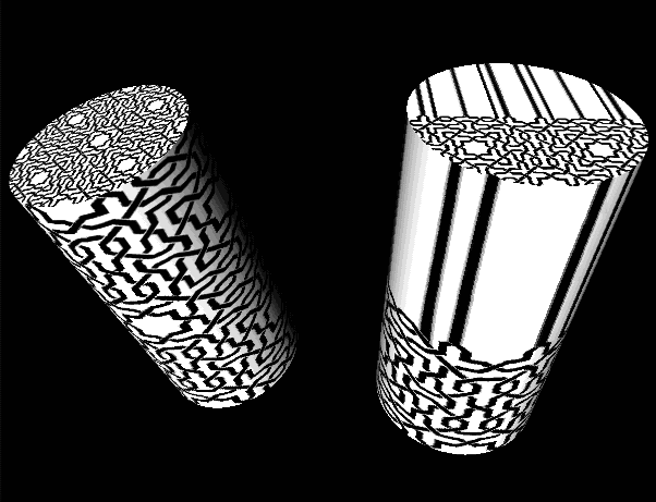
Figure 7.3, “ Wrapping the Texture around the Object ” shows examples of both types of wrapping. The cylinder on the left has the texture repeated twice along its length and around its circumference. The cylinder on the right has the top scanline clamped, by setting wrapT to CLAMP. See Section 7.3, “Texture Nodes” for a description of the wrapS and wrapT fields.
You can specify one of three texture models to use (see Section 7.3, “Texture Nodes”). Each model causes the texture map to affect the underlying colors of the polygon in different ways. The model types are as follows:
The MODULATE model can be used with any texture file. The BLEND model is used with one- or two-component files. The DECAL model is used with three- or four-component files. See the section called “Components of a Texture”.
![[Tip]](../images/tip.jpg) | |
Tip: MODULATE works best on bright materials because the texture intensity, which is less than or equal to 1.0, is multiplied by the shaded color. |
Figure B.10, “ Plate 10 ” through Figure B.13, “ Plate 13 ” show examples of each texture model. The image in Figure B.10, “ Plate 10 ” shows the scene without a texture. The image in Figure B.11, “ Plate 11 ” uses a MODULATE model, so the color of the building is a combination of the texture and material colors. The image in Figure B.12, “ Plate 12 ” uses a DECAL model, so the color of the building is determined completely by the texture map. The image in Figure B.13, “ Plate 13 ” uses the BLEND model, so the color of the building blends between the underlying material color and the blend color value (gold).
| |
Tip: To create bright green polka dots on an object, create a black and white texture with white dots. Then use the BLEND texture model with a green blend color. |
See the glTexEnv() function in the OpenGL Reference Manual for the actual equations used to calculate the final textured object colors.
| |
Tip: If you use MODULATE, you may want to surround your texture images with a one-pixel border of white pixels and set wrapS and wrapT to CLAMP so that the object's color is used where the texture runs out. |
Texture maps are read from a file or from memory. For information on what image file formats your platform supports, see your release documentation.
You can store a texture map as an SoSFImage( C++ | Java | .NET ) and then specify the image in the image field of the SoTexture2( C++ | Java | .NET ) node. This section provides details on how to store the texture-map pixels in memory. The texture, whether stored in a file or in memory, can contain from one to four components, as described in the following section.
A texture can be one of the following types:
One-component texture—contains only an intensity value. This type of texture is often referred to as an intensity map. For example, an image of a mountain could use a one-component texture and vary the intensity of a constant-color polygon to make the image more realistic.
Two-component texture—contains an intensity value and an alpha (transparency) value. For example, you can create a tree with leaves made of polygons of varying intensity, from dark green to bright green. Then, you can vary the transparency at the edges of the leaf
area, so that you can see around the edges of the leaves to the objects behind them.
Three-component texture—contains red, green, and blue values. This is a red-green-blue image, such as a photo or a commonly used texture such as brick, concrete, or cloth.
Four-component texture—contains red, green, blue, and alpha (transparency) values. This texture is similar to the RGB three-component texture, but also contains transparency information. You can use a four-component texture to create a colorful New England maple tree in October using the technique described previously for two-component textures.
| |
Tip: One- and two-component textures are generally faster than three- and four-component textures, since they require less computation. |
Use the setValue() method to assign the value to the SoSFImage( C++ | Java | .NET ). This method requires you to supply the size of the texture (width * height, in pixels), the number of components in the texture, and the values of the components for each pixel (as an array of unsigned chars, with values 0 to 255).
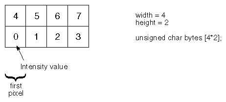
For a one-component texture, each byte in the array stores the intensity value for one pixel. As shown in Figure 7.4, “ Format for Storing a One-Component Texture in Memory ”, byte 0 is the lower left corner of the pixel map, and numbering of bytes is from left to right within each row.
For example, to store a one-component texture, the code would be
C++
SoTexture2 *textureNode = new SoTexture2;
// A 3-by-2 array of black and white pixels; the array is
//upside-down here (the first pixel is the lower left corner)
unsigned char image [] = {
   255, 0,
   0, 255,
   255, 0
};
//Set the image field:
textureNode->image.setValue(SbVec2s(3,2), 1, image);
.NET
SoTexture2 textureNode = new SoTexture2();
// A 3-by-2 array of black and white pixels; the array is
//upside-down here (the first pixel is the lower left corner)
byte[] image = new byte[]{
   255, 0,
   0, 255,
   255, 0
};
//Set the image field:
textureNode.image.SetValue(new SbVec2s(3,2), 1, image);
Java
SoTexture2 textureNode = new SoTexture2();
// A 3-by-2 array of black and white pixels; the array is
//upside-down here (the first pixel is the lower left corner)
byte[] image = new byte[]
{
  (byte)255, (byte)0,
  (byte)0,   (byte)255,
  (byte)255, (byte)0
};

//Set the image field:
textureNode.image.setValue(new SbVec2s((short)3, (short)2), 1, image);
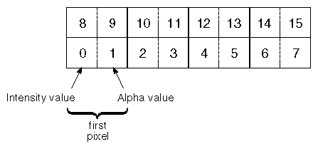
For a two-component texture, byte 0 is the intensity of the first pixel, and byte 1 is the alpha (transparency) value for the first pixel. Bytes 2 and 3 contain the information for pixel 2, and so on (see Figure 7.5, “ Format for Storing a Two-Component Texture in Memory ”).
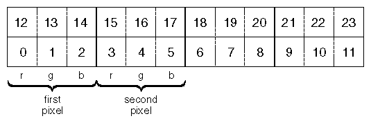
A three-component texture requires three bytes to store the information for each pixel. For the first pixel, byte 0 contains the red value, byte 1 contains the green value, and byte 2 contains the blue value (see Figure 7.6, “ Format for Storing a Three-Component Texture in Memory ”). A four-component texture requires four bytes for each pixel (red, green, blue, and alpha values).
SoRenderToTextureProperty( C++ | Java | .NET ) specifies a 2D texture image which is the result of rendering a scene graph. This scene graph rendering is done using OpenGL Pbuffer and render-to-texture features (if supported). The texture image is automatically re-rendered if the supplied scene graph is modified. Note that the supplied scene graph should normally contain a camera node and a light node.
The SoRenderToTextureProperty( C++ | Java | .NET ) node is specified in the renderToTextureProperty field of SoTexture2( C++ | Java | .NET ) and SoTextureCubeMap( C++ | Java | .NET ).
SoRenderToTextureProperty( C++ | Java | .NET ) has the following fields:
node (SoMFNode) | Specifies the scene graph (SoNode( C++ | Java | .NET )) to be rendered into the texture. If this node is to be used with SoTexture2( C++ | Java | .NET ), only one node should be specified. For use with SoTextureCubeMap( C++ | Java | .NET ), six nodes must be supplied. The node field takes precedence over the path field. Null by default. |
path (SoMFPath) | Specifies the scene graph (SoPath( C++ | Java | .NET )) to be rendered into the texture. If this node is to be used with SoTexture2( C++ | Java | .NET ), only one path should be specified. For use with SoTextureCubeMap( C++ | Java | .NET ), six paths must be supplied. The node field takes precedence over the path field. Null by default. |
updatePolicy (SoSFEnum) | Specifies the policy for rendering to the texture. WHEN_NEEDED by default. |
backgroundColor (SoSFColor) | Background color used when rendering the scene graph. Black by default. |
size (SoSFVec2s) | Size in pixels of the rendered texture. (0,0) by default. |
component (SoSFEnum) | Specifies the type of component(s) for rendering. RGB by default. |
trigger (SoSFTrigger) | Trigger field to start the rendering. Effective only if the updatePolicy is ON_TRIGGER. |