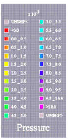
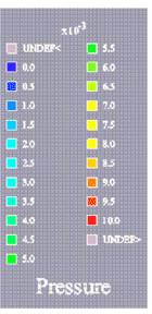
In GraphMaster we have seen how to associate a legend with a curve visualization using PoItemLegend( C++ | Java | .NET )node. Other legend nodes derived from PoLegend( C++ | Java | .NET )are very useful in 3DdataMaster. These legends will allow you to visualize the data-color mapping and to “explain” your results.
3DdataMaster provides two main types of legends: automatic and non-automatic. Automatic legends will specify the geometry of inside “items” on their own, unlike non-automatic legends where your application must specify the geometry of each item.
To create a legend, you must go through the following steps:
Create the legend node by specifying its geometry and attributes (size of the legend box, number of columns, title, value positions, etc.)
Associate, if necessary, a data mapping by inserting a PoDataMapping( C++ | Java | .NET )object in the scene graph.
Associate, if necessary, a list of isovalues by inserting a PoIsovaluesList( C++ | Java | .NET )object in the scene graph.
Specify which values you want to be displayed by setting the firstValue ,lastValue , and periodValuefields of the legend node. You can also choose to display values from the data mapping or the isovalue list node using the same method as for graduations along a linear axis. And finally you can choose to display only the bounding values, per the valueDistributionfields of some of the legend nodes.
Add the legend to the scene graph.
![[Note]](../../images/note.jpg) | |
If you only set data mapping, then the legend will use the minimum and maximum values of the data mapping definition as its bounding values. In some cases, the data mapping does not define any bounding values, and thus you must then specify the isovalue list or at least its bounding values. If you set the isovalue list, 3DdataMaster will use the data mapping to determine which color is associated with each value. |
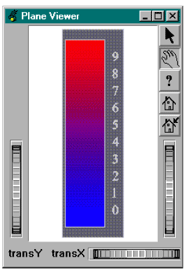
The following example (located in $OIVHOME/src/MeshViz/Mentor) shows a way to build a legend, using data mapping and an isovalues list:
Example 2.33. Use of value legend

C++
// tutorialMesh02.cxx

#include <Inventor/Xt/SoXt.h>
#include <Inventor/Xt/viewers/SoXtPlaneViewer.h>
#include <Inventor/nodes/SoAnnotation.h>
#include <MeshViz/graph/PoLinearValueLegend.h>
#include <MeshViz/nodes/PoLinearDataMapping.h>
#include <MeshViz/nodes/PoIsovaluesList.h>

int
main(int, char **argv)
{
// Initialize Inventor and Xt
Widget myWindow = SoXt::init(argv[0]);
  if (myWindow == NULL) exit(1);

// Initialize MeshViz
  PoMeshViz::init();

// Define the data-color mapping
  PoLinearDataMapping *myDataMapping = new PoLinearDataMapping;
  myDataMapping->color1 = SbColor(0,0,1);
  myDataMapping->value1 = 0;
  myDataMapping->color2 = SbColor(1,0,0);
  myDataMapping->value1 = 10;

// Define list of values
  PoIsovaluesList *myList = new PoIsovaluesList;
  myList->setRegularIsoList(0.,9.,10);

// Create the legend node
  PoLinearValueLegend *legend =
     new PoLinearValueLegend(SbVec2f(0.,0.), SbVec2f(0.3, 1.0));
  legend->set("backgroundApp.material", "diffuseColor .4 .4 .4");

// Create the root of our scene graph
  SoAnnotation *root = new SoAnnotation;
  root->ref();
  root->addChild(myDataMapping);
  root->addChild(myList);
  root->addChild(legend);

  SoXtPlaneViewer *viewer = new SoXtPlaneViewer(myWindow);
  viewer->setBackgroundColor(SbColor(1., 1., 1.));
  viewer->setSceneGraph(root);
  viewer->show();

  SoXt::show(myWindow);
  SoXt::mainLoop();
  return 0;
}


