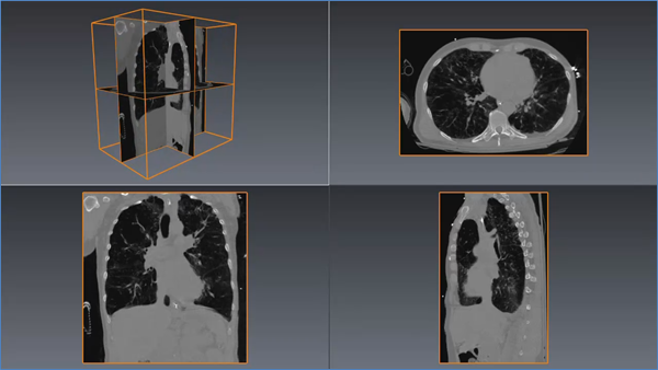
This node defines an axis aligned slice along the X, Y, or Z axis of the volume. Ortho slices can represent sagittal, coronal and transverse slices in medical imaging or represent line, cross-line and time slices in seismic imaging. When a stack of images is loaded, the images are the slices along the volume’s Z axis. We have already seen an example of SoOrthoSlice( C++ | Java | .NET ) in Section 1.1.4, “Quick Start”. The code fragment below extends the previous one to draw two perpendicular slices.
The slice axis and position are defined by the axis and sliceNumber fields. Note that ortho slices are drawn at the “center” of the voxel specified by the sliceNumber field. The extent of the volume is its bounding box in 3D space. So we can consider that each voxel has an extent in 3D defined by the volume extent along each axis divided by the volume dimension (number of voxels) along that axis. It is just as correct to consider this the “voxel spacing”, but for this discussion we will consider that voxels have extent. So the first slice (slice 0) will be offset one-half the voxel size from the volume’s minimum 3D coordinate on the slice axis. This is in contrast to SoVolumeSkin( C++ | Java | .NET ) which draws its slices at the outer edge of the voxel.
Optionally, this node can also define a clipping plane. Similar to SoClipPlane( C++ | Java | .NET ), this is an OpenGL clipping plane that affects all subsequent geometry, including SoVolumeRender( C++ | Java | .NET ). The clipping and clippingSide fields control whether clipping is active and which half-space is clipped.
All the usual slice properties for appearance and clipping apply to ortho slices. It is possible to use an SoTranslate1Dragger( C++ | Java | .NET ) to drag a slice through the volume, however it is not possible to directly connect the dragger to the slice because the dragger works in 3D coordinates and the slice is positioned in voxel coordinates. The application needs to specify a valueChanged callback for the dragger and update the sliceNumber field in the callback. For convenience VolumeViz provides the SoOrthoSliceDragger( C++ | Java | .NET ) class which handles this conversion and substitutes the geometry of the slice for the default geometry of an SoTranslate1Dragger( C++ | Java | .NET ).
![[Important]](../../images/important.jpg) | |
For performance reasons, SoOrthoSlice( C++ | Java | .NET ) accumulates small textures into a bigger one. When using compressed RGBA textures (via SoDataSet( C++ | Java | .NET )'s field useCompressedTexture), this optimization cannot be done. If you want to favor performance rather than memory usage, you should disable compression (enabled by default if supported by the graphic card) |
C++
SoOrthoSlice* pSliceX = new SoOrthoSlice;
pSliceX->axis = SoOrthoSlice::X;
pSliceX->sliceNumber = 128;
[SoOrthoSlice* pSliceZ = new SoOrthoSlice;
pSliceZ->axis = SoOrthoSlice::Z;
pSliceZ->sliceNumber = 55;
.NET
SoOrthoSlice SliceX = new SoOrthoSlice();
SliceX.axis.Value = SoOrthoSlice.AxisType.X;
SliceX.sliceNumber.Value = 128;
[SoOrthoSlice SliceZ = new SoOrthoSlice();
SliceZ.axis.Value = SoOrthoSlice.AxisType.Z;
SliceZ.sliceNumber.Value = 55;
Java
SoOrthoSlice sliceX = new SoOrthoSlice();
sliceX.axis.setValue( SoOrthoSlice.AxisType.X );
sliceX.sliceNumber.setValue( 128 );
SoOrthoSlice sliceZ = new SoOrthoSlice();
sliceZ.axis.setValue( SoOrthoSlice.AxisType.Z );
sliceZ.sliceNumber.setValue( 55 );
VolumeViz does not support thickness as a slice property. However a "thick slice" (also known as "thin slab") rendering can be easily achieved using volume rendering (SoVolumeRender( C++ | Java | .NET )) and a region of interest (SoROI( C++ | Java | .NET )). See Section 1.7.1, “Region of Interest”