Generally speaking, slices are a planar surface or a collection of planar surfaces, on which VolumeViz displays colors mapped from the values of the voxels that are intersected by the surface(s). Axis aligned slices (called ortho slices in VolumeViz) are the traditional first tool for exploring the data in a volume, but VolumeViz supports more complex slice types for specific purposes, including application defined slices (called volume geometry here) which can be curved surfaces, cylinders and so on. The slice primitives generally provide high performance and high image quality compared to volume rendering, but compared to volume rendering can only provide clues about the internal structure of the volume. All the slice type primitives, except volume geometry, are derived from the base class SoSlice( C++ | Java | .NET ).
The appearance of slice primitives is primarily determined by the SoMaterial( C++ | Java | .NET ), SoDataRange( C++ | Java | .NET ) and SoTransferFunction( C++ | Java | .NET ) (color map) nodes described in Section 1.3, “Appearance”. The appearance of slices is also affected by slice specific properties including alphaUse, interpolation and bump mapping which are described in this section. In addition, custom shader functions may be applied to slices for special computation or rendering effects, for example co-blending multiple volumes, as described in Section 1.8, “Shaders” and Section 1.9, “Transforming and Combining Volumes”.
Lighting
Like other Open Inventor geometry, the appearance of slice primitives is automatically affected by light nodes in the scene graph, e.g. the viewer headlight and SoDirectionalLight( C++ | Java | .NET ) nodes. Like other geometry, lighting can give important visual cues about the shape of objects and the relationships of objects in the scene. For slices, lighting is particularly useful for highlighting where two or more slices intersect (one of the slices will typically be brighter than the other because it is more perpendicular to the camera). Lighting is also useful for highlighting the bump mapping effect. However when interpreting the color of voxels on a slice the user must be aware that lighting modifies the intensity (and possibly the color) of the slice. By default, turning off all lights in the scene will cause slices to be rendered black. To prevent lighting from affecting a slice and render with its true colors, use an SoLightModel( C++ | Java | .NET ) node with the model field set to BASE_COLOR.
VolumeViz supports the complete Open Inventor lighting model (which is the same as the OpenGL lighting model). So when lighting is enabled, you can control the ambientColor, specularColor, shininess and other properties of voxels using an SoMaterial( C++ | Java | .NET ) node. Lighting is enabled by default for slice and height field primitives. Multiple lights are supported and the light color, intensity and direction (see SoLight( C++ | Java | .NET ) and subclasses) affect rendering. For convenience, two-sided lighting is automatically enabled for slice primitives (but not for height field primitives).
Shadows
Like other Open Inventor geometry, when lighting is enabled slice primitives can cast and receive shadows. Shadows may be useful in some applications to give visual cues about the relationships (particularly depth ordering) of objects in the scene. To enable shadows, put the slice primitives under an SoShadowGroup( C++ | Java | .NET ) node and set its method field to VARIANCE_SHADOW_MAP.
Transparency
Slices can be made partially transparent using SoMaterial( C++ | Java | .NET ) or the transfer function. Correctly rendering scenes containing transparent geometry is complex and can reduce rendering performance. The transparency rendering mode is specified using the setTransparencyType() method in the Open Inventor viewer class (or the SoGLRenderAction( C++ | Java | .NET )). When using opaque slices, which is often the case, one of the basic transparency modes like DELAYED_BLEND should be sufficient to get the correct image. When using transparent slices it is usually necessary to use the most complex transparency mode DELAYED_SORTED_LAYERS_BLEND. In extreme cases it may be necessary to increase the number of rendering passes using the setSortedLayersNumPasses() method in SoGLRenderAction( C++ | Java | .NET ).
Clipping
The geometry of slices can be clipped by clip planes (SoClipPlane( C++ | Java | .NET )), region of interest (SoROI( C++ | Java | .NET )), polygonal shapes (SoVolumeClippingGroup( C++ | Java | .NET )), height field surfaces (SoUniformGridClipping( C++ | Java | .NET )) and mask volumes (SoVolumeMask( C++ | Java | .NET )) as described in Section 1.7, “Clipping”.
Interaction
By default slices are pickable (even where transparent) and the respective slice detail classes, for example SoOrthoSliceDetail( C++ | Java | .NET ) allow you to query the position and value of the picked voxel. Open Inventor draggers (see SoDragger( C++ | Java | .NET )) can be used to implement interactive dragging, rotation, etc of slices.
Whether the alpha (opacity) value comes from an RGBA value or the color map, the alphaUse field controls how a slice primitive uses that value. The default value is ALPHA_BINARY meaning that an alpha value of zero is fully transparent as usual, but all non-zero alpha values are considered completely opaque. The ALPHA_AS_IS value means to interpret alpha values in the usual way as a fraction of opacity. The ALPHA_OPAQUE value means to ignore alpha values and render the slice as completely opaque. This is useful because color maps for volume rendering typically have (at least some) low alpha values. The ALPHA_OPAQUE value allows the convenience of using the same color map for both volume rendering and for slices, but still having opaque slices.
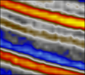
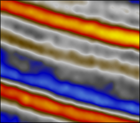
Slices are rendered using OpenGL texture mapping and a 2D texture extracted from the data volume. The interpolation field (inherited from SoVolumeShape( C++ | Java | .NET )) controls how data values (or color values in the case of an RGBA volume) are interpolated for locations that do not fall precisely on a voxel center. NEAREST uses OpenGL “nearest neighbor” interpolation. It produces a “blocky” rendering but can be useful to see the voxel positions. The default value LINEAR uses hardware accelerated bi-linear interpolation. TRILINEAR improves image quality for SoObliqueSlice( C++ | Java | .NET ) nodes that are rotated away from the primary axes of the volume (it’s the same as LINEAR for other nodes). MULTISAMPLE_12 is an advanced interpolation algorithm based on antialiasing techniques. It uses staggered samples from 12 neighbors of the sample point to avoid coloring artifacts introduced by the hardware rasterizer. It provides the best image quality but has a small performance penalty because it is implemented using a GLSL shader. MULTISAMPLE_12 applies to SoOrthoSlice( C++ | Java | .NET ), SoObliqueSlice( C++ | Java | .NET ), SoFenceSlice( C++ | Java | .NET ) and SoVolumeSkin( C++ | Java | .NET ). MULTISAMPLE_12 does not apply to volume rendering, but SoVolumeRender( C++ | Java | .NET ) provides a higher quality mode specific to volume rendering, called cubic interpolation.
|
|
|
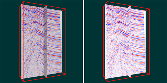
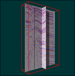
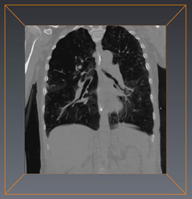
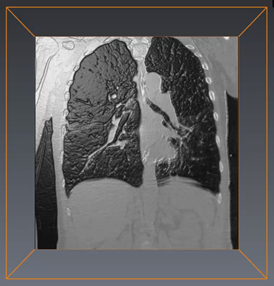
Most slice primitives can render using a bump mapping effect. Bump mapping is a rendering effect that simulates displacement of the slice surface using the gradient vectors (computed on the GPU) as normal vectors. This effect can be useful to highlight areas of the image where the gradient is changing rapidly. Normally lighting should be enabled to maximize the visual effect of bump mapping. However for slices bump mapping works well with the default viewer “headlight”, which is enabled by default. Bump mapping is enabled using the enableBumpMapping field (inherited from SoSlice( C++ | Java | .NET )) and the intensity of the effect can be controlled using the bumpScale field. Bump mapping is not available for the SoHeightFieldRender( C++ | Java | .NET ) node or for volume geometry (e.g. SoVolumeIndexedFaceSet( C++ | Java | .NET )). Bump mapping is enabled in the right-hand image below. In this case the light source (SoDirectionalLight( C++ | Java | .NET ) node) has been rotated so the light strikes the “bumps” at an angle.
|
|
|
Some slice primitives (currently SoOrthoSlice( C++ | Java | .NET ) and SoVolumeSkin( C++ | Java | .NET )) support the large slice data loading feature. This feature allows a slice to be displayed at full resolution even if the required LDM tiles are not currently in memory and even if there is not enough memory available to load all of the required LDM tiles. When large slice support is enabled and the required tiles are already in LDM cache memory, the slice data is read from the LDM cache as usual. If the required tiles are not available, the slice data is requested directly from the volume reader (typically meaning directly from the volume data file). Note that only the data for the slice is loaded, not the complete tiles. So less data is transferred from disk and less system memory is required. This may allow slices to be displayed at full resolution even when there is not enough system memory to hold all the necessary full resolution files. For example, loading a 1024x1024 SoOrthoSlice( C++ | Java | .NET ) from an 8-bit dataset with 128x128x128 tiles would normally require loading 1024x1024x128 bytes of data (as complete tiles). With largeSliceSupport enabled, a maximum of 1024x1024 bytes of data need to be loaded (in the worst case where no high resolution data is currently in memory).
LDM schedules the missing tiles to be loaded asynchronously in the background. This may accelerate the loading of the data for a subsequent slice intersecting the same set of tiles.
![[Important]](../../images/important.jpg) | |
Currently the large slice feature does not support asynchronous loading. This means that no rendering can be done until all the data needed to build the slice has been read. |
The slice nodes (except volume geometry) have an alternateRep field, similar to the MeshViz nodes. This field can optionally contain a scene graph which is an “alternate representation” of the node, using only standard texture and faceset nodes. When reading a “.iv” file Open Inventor will automatically use the alternate representation scene graph if it does not recognize the node type. This allows volume slices created in a VolumeViz application to be read and displayed correctly in any Open Inventor-based program, for example SceneViewer, even if that program does not initialize the VolumeViz extension.
The application program can set any scene graph into the alternateRep field before writing an “.iv” file, but this is usually not necessary. VolumeViz can automatically generate an alternateRep scene graph for slice nodes. The setWriteAlternateRep() method in SoVolumeRendering( C++ | Java | .NET ) enables this behavior. Open Inventor “.iv” files that contain this field will not be readable by applications using an Open Inventor version less than 4.0. However this field will not be written out unless specifically requested by the application.
Normally when VolumeViz nodes with an alternate representation are read into a VolumeViz-enabled application (i.e., SoVolumeRendering( C++ | Java | .NET )::init() was called), the alternative representation is not stored in the scene graph (to save memory). You can override this behavior using the setReadAlternativeRep() method in SoVolumeRendering( C++ | Java | .NET )