SoROI Class Reference
[Nodes]
 Region of Interest (subvolume) node.
More...
Region of Interest (subvolume) node.
More...
#include <LDM/nodes/SoROI.h>
Public Types | |
| enum | Flags { ENABLE_X0 = 0x1, ENABLE_Y0 = 0x2, ENABLE_Z0 = 0x4, INVERT_0 = 0x8, ENABLE_X1 = 0x10, ENABLE_Y1 = 0x20, ENABLE_Z1 = 0x40, INVERT_1 = 0x80, ENABLE_X2 = 0x100, ENABLE_Y2 = 0x200, ENABLE_Z2 = 0x400, INVERT_2 = 0x800, OR_SELECT = 0x1000, INVERT_OUTPUT = 0x2000, SUB_VOLUME = ENABLE_X0 | ENABLE_Y0 | ENABLE_Z0, EXCLUSION_BOX = SUB_VOLUME | INVERT_OUTPUT, CROSS = ENABLE_X0 | ENABLE_Y0 | ENABLE_Y1 | ENABLE_Z1 | ENABLE_X2 | ENABLE_Z2 | OR_SELECT, CROSS_INVERT = CROSS | INVERT_OUTPUT, FENCE = ENABLE_X0 | ENABLE_Y1 | ENABLE_Z2 | OR_SELECT, FENCE_INVERT = FENCE | INVERT_OUTPUT } |
Public Member Functions | |
| virtual SoType | getTypeId () const |
| SoROI () | |
Static Public Member Functions | |
| static SoType | getClassTypeId () |
Public Attributes | |
| SoSFInt32 | dataSetId |
| SoSFBox3i32 | box |
| SoSFBitMask | flags |
| SoSFBox3i32 | subVolume |
| SoSFBool | relative |
Detailed Description
Region of Interest (subvolume) node.
The ROI ("region of interest") node allows you to specify a sub-region of the volume that will be rendered. Voxels within the ROI are rendered; voxels outside the ROI are not rendered. This provides a simple and very efficient form of volume clipping (much more efficient than using SoClipPlane nodes).
The SoVolumeData node on which the ROI will be applied can be specified with dataSetId. When this field is set to 0, the last SoVolumeData node on state is used.
In addition, for large volumes that cannot be fully loading into CPU and/or GPU memory, SoROI can improve both data loading performance and image quality. VolumeViz will always try to load the highest resolution data possible for the voxels inside the region defined by the ROI. VolumeViz is not required to load data in tiles that are completely outside the ROI. VolumeViz may load tiles outside the ROI if there is sufficient memory (this is useful in cases where the user can move or resize the ROI). But in general, for large volumes, using SoROI reduces the amount of data that must be loaded and increases image quality for the voxels inside the ROI.
Note that the above discussion only applies in multi-resolution mode (the default). In fixed resolution mode (see SoLDMResourceParameters::fixedResolution), VolumeViz will try to load all the tiles in the volume at the specified resolution level regardless of the SoROI settings.
The ROI can be a simple box (default) or a complex shape defined by (up to) three box shapes (X, Y, and Z slabs) and logic flags that specify how the slabs are to be combined.
SoROI is commonly used with an opaque color map to provide a "volume probe" in seismic data applications. However it is useful with any kind of volume data to limit the data displayed and to improve loading and image quality as discussed above.
The box and subVolume fields are specified in voxel coordinates. The limits are included in the ROI. A value of 0,0,0 0,0,0 (min and max) in the subVolume field means that this field should be ignored. This is the default.
This node acts on the rendering shape nodes of VolumeViz (SoVolumeRender, SoOrthoSlice, SoObliqueSlice, SoVolumeSkin, etc.)
To define a simple ROI, set the limits of the ROI in the box field (and do not set the subVolume field). The same result is obtained by setting the box and subVolume fields to the same value, but this is not necessary. But note that the default ROI box is not automatically the full volume. You must initialize the ROI box to something, for example the volume dimensions minus one.
      // Initialize ROI box to full volume
      SoVolumeData* volData = new SoVolumeData();
      . . .
      SoROIManip*   roiManip = new SoROIManip();
      roiManip->box.setValue( SbVec3i32(0,0,0), volData->data.getSize() - SbVec3i32(1,1,1) );
      root->addChild( roiManip );
For a complex ROI, the region defined by the SoROI box field always acts upon the region defined by the SoROI subVolume field, not the entire volume. For example, in EXCLUSION_BOX mode, the visible portion of the volume is the subVolume region minus the box region. You are allowed to set the box region larger than (or completely outside) the subVolume region, but only the intersection of the two regions is significant.
You can also use the convenient manipulator class SoROIManip to allow your users to interactively move and resize the region of interest.
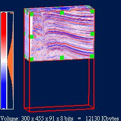
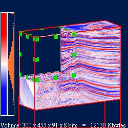
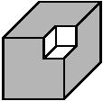
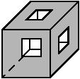
The figures below show the subVolume field used to limit the visible portion of the volume (left) and the ROI used as an "exclusion box" to cut away part of the subvolume (right).
| Example: box field used to limit visible portion of the volume |
|
| Example: box field + subVolume field used as an exclusion box |
|
The Crop Box and Cropping Process.
The crop box is defined by three sets of parallel planes that define three slabs:
- The xmin and xmax planes define the X slab.
- The ymin and ymax planes define the Y slab.
- The zmin and zmax planes define the Z slab.
After these three planes have been specified, cropping is done in four stages.
Stage 1 determines which voxels to include relative to one or more of the slabs. Classification can be enabled or disabled relative to the X slab, Y slab, or Z slab. This classification is performed three separate times, resulting in three terms: Term 0, Term 1, and Term 2. Each term has its own logic flags that enable the three slabs, independent of the other terms. The flags are as follows:
- Enable or disable classification relative to the X slab.
- Enable or disable classification relative to the Y slab.
- Enable or disable classification relative to the Z slab.
Stage 2 determines whether to invert the values obtained in Stage 1 so that the voxels outside a slab are selected. This determination is made for each of the terms (Term 0, Term 1, Term 2). As in Stage 1, each term has its own inversion flag and is independent of the other terms.
Stage 3 creates either the union or the intersection of Term 0, Term 1, and Term 2. This is specified using a logic flag.
Stage 4 determines whether to invert the result of Stage 3 and provides the final ROI. Again, the inversion (if any) is specified using a logic flag.
Example of Cropping Process
(Figures courtesy Real Time Visualization)
The following example will show you how the cropping process works.
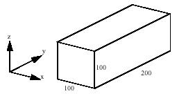
Start with a volume that is 100x200x100 (x, y, z). The final cropped shape will be the union of a 20x200x20 bar and a 100x25x100 box.
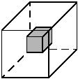
Here is the initial volume:
Here is the bar:
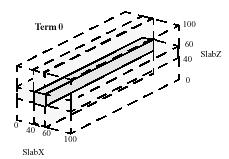
The bar can be formed in Term 0 of Stage 1 by using the intersection of the X and Z slabs, each with min and max values set to 40 and 60, respectively.
Here is the box:
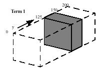
The box can be formed in Term 1 of Stage 1 by using just the Y slab, with min and max values set to 125 and 150.
Term 2 of Stage 1 can be set to be identical to Term 0 or Term 1, or it can be set to include no samples by setting no enable flags (no slabs selected, so entire volume is selected) and setting the invert flag of Stage 2 so that the entire volume is deselected. To get the union of these terms in Stage 3, OR_SELECT is set. That results in the desired cropping, so Stage 4, in which the results are inverted, is not used.
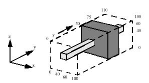
Here is the code to set the box dimensions and the logic flags:
      SoROI* myROI = new SoROI();
      int xmin =  40; int xmax =  60;
      int ymin = 125; int ymax = 150;
      int zmin =  40; int zmax =  60;
      myROI->box.setValue( xmin, ymin, zmin, xmax, ymax, zmax );
      myROI->flags = SoROI::ENABLE_X0 | SoROI::ENABLE_Z0 | SoROI::ENABLE_Y1 | SoROI::INVERT_2 | SoROI::OR_SELECT;
Here is the resulting complex crop box:
Additional Examples
| Example 1: flags = SUB_VOLUME
Alternate setting:flags = ENABLE_X0 | ENABLE_Y1 | ENABLE_Z2 |
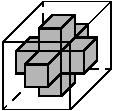
| Example 2: flags = FENCE
Alternate setting:flags = ENABLE_X0 | ENABLE_Y1 | ENABLE_Z2 | OR_SELECT |
| Example 3: flags = FENCE
Note that example 2 and 3 have the same flags set; but in example 2, xmin, ymin, and zmin values are set to zero. Setting its xmax, ymax, and zmax values to the maximum value produces a similar crop. |
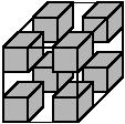
| Example 4: flags = FENCE_INVERT
Alternate setting:flags = ENABLE_X0 | ENABLE_Y1 | ENABLE_Z2 | OR_SELECT | INVERT_OUTPUT |
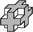
| Example 5: flags = CROSS
Alternate setting:flags = ENABLE_X0 | ENABLE_Y0 | ENABLE_Y1 | ENABLE_Z1 | ENABLE_X2 | ENABLE_Z2 | OR_SELECT |
| Example 6: flags = CROSS_INVERT
Alternate setting:flags = CROSS | INVERT_OUTPUT |
FILE FORMAT/DEFAULT
- ROI {
| dataSetId | 0 |
| subVolume | 0, 0, 0, 0, 0, 0 |
| box | 0, 0, 0, 1, 1, 1 |
| flags | 7 |
| relative | FALSE |
LIMITATIONS Only one ROI per volume data can be used at same time.
SEE ALSO
SoVolumeRender, SoOrthoSlice, SoObliqueSlice, SoROIManip
ACTION BEHAVIOR
- SoCallbackAction, SoGLRenderAction, SoGetBoundingBoxAction, SoPickAction, SoWriteAction
- See related examples:
-
MedicalComputeHistogram, MedicalRotateROI, ComputeHistogram, VolRend
- Enumerator:
- LDM/nodes/SoROI.h
Member Enumeration Documentation
| enum SoROI::Flags |
Flag value mask.
Constructor & Destructor Documentation
| SoROI::SoROI | ( | ) |
Constructor.
Member Function Documentation
| static SoType SoROI::getClassTypeId | ( | ) | [static] |
| virtual SoType SoROI::getTypeId | ( | ) | const [virtual] |
Returns the type identifier for this specific instance.
Reimplemented from SoNode.
Reimplemented in SoROIManip.
Member Data Documentation
Specifies which SoVolumeData node to use.
This is useful when datasets of different dimensions are present in the scene graph. Please see SoMultiDataSeparator for more details.
When set to 0, the last SoVolumeData node on state is used. Default is 0.
NOTE: field available since Open Inventor 10.11.0Specifies how the bounds of the box are used.
Default is SUB_VOLUME. The region of interest is the box itself.
Specifies whether the box bounds are relative to the subvolume or the full volume (i.e., are specified in absolute slice coordinates).
TRUE means that if the subvolume is non-empty, moving the subvolume through the volume also moves the ROI box through the volume. Default is FALSE.
Specifies the bounds of the subvolume that will be rendered.
By default, it is an empty box and has no effect. The subvolume is always a simple box.
The documentation for this class was generated from the following file: