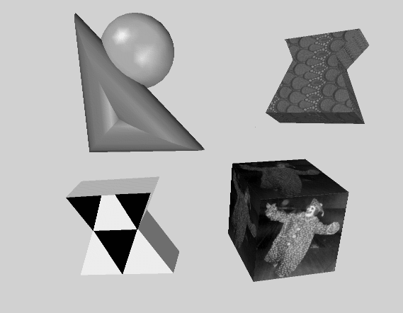
Using textures, you can create a table with a wood grain, an orange with a dimpled, shiny surface, and a field of grass. To do so, first create wood, orange peel, and grass textures and then apply the textures to the various shape objects. Figure 7.1, “ Texture Mapping ” contrasts two sets of objects: the objects on the right use texture mapping, and the objects on the left do not use textures.
A texture map is a 2D image that is applied to a surface of a geometric object. It is an array of pixel information that is read from a file or from memory. Its coordinates are normalized to range from 0.0 to 1.0 in both the s (horizontal) and t (vertical) directions. If the texels in the texture image do not correspond exactly to pixels on the screen, Open Inventor uses a filtering process to cover the polygon properly.
A 3D texture map is similar to a 2D texture map, but with three dimensions. This is a 3D array of texel information that is read from files or from memory. Its coordinates are normalized to range from 0.0 to 1.0 in all three directions: s (horizontal), t (vertical), and r (depth).
Cube map textures are a set of six two-dimensional texture images mapped onto the six faces of a cube centered at the origin. The texture coordinates (s, t, r) are used as a direction vector pointing from the origin. The greatest coordinate is used to select the face and the two others to select a texel from that face. Cube maps are well suited for mapping a reflection of the environment onto an object. (This is also possible using sphere mapping (SoTextureCoordinateEnvironment SoTextureCoordinateEnvironment SoTextureCoordinateEnvironment ), but only with a specially distorted image.)
This section describes use of the following node classes:
specifies a 2D texture map to be used and associated parameters for texture mapping. | |
SoTextureCoordinate2 SoTextureCoordinate2 SoTextureCoordinate2 | explicitly defines the set of 2D texture coordinates to be used by subsequent vertex shapes. |
SoTextureCoordinateBinding SoTextureCoordinateBinding SoTextureCoordinateBinding | specifies how the current texture coordinates are to be bound to subsequent shape nodes. |
SoTextureCoordinatePlane SoTextureCoordinatePlane SoTextureCoordinatePlane | SoTextureCoordinateEnvironment SoTextureCoordinateEnvironment SoTextureCoordinateEnvironment allow you to use a function to map from spatial coordinates to texture coordinates. |
SoTextureCoordinateDefault SoTextureCoordinateDefault SoTextureCoordinateDefault | turns off any previous texture-coordinate function so that all following shapes use their default texture coordinates. |
defines a 2D transformation for the texture map. |
The SoComplexity SoComplexity SoComplexity node has a textureQuality field that relates to texture mapping as well. It allows you to specify a value between 0.0 and 1.0, with 0.0 for the fastest rendering and 1.0 for the finest texturing. (In general, there is a trade-off between speed and the quality of texturing.) The default value for this field is 0.5.
Although you can affect how a texture is applied to an object in many ways, the simplest way to use textures is to use the default values. If you use textures, you need only an SoTexture2 SoTexture2 SoTexture2 node (for the texture) and a shape node (the target object). Example 7.1, “ Using the Default Texture Values ”, which displays a textured cube, illustrates this method. See Section 7.3, “Texture Nodes” for a detailed description of the SoTexture2 SoTexture2 SoTexture2 node and its defaults.
Example 7.1. Using the Default Texture Values
#include <Inventor/Xt/SoXt.h>
#include <Inventor/Xt/viewers/SoXtExaminerViewer.h>
#include <Inventor/nodes/SoCube.h>
#include <Inventor/nodes/SoSeparator.h>
#include <Inventor/nodes/SoTexture2.h>

main(int , char **argv)
{
   Widget myWindow = SoXt::init(argv[0]);
   if(myWindow == NULL) exit(1);

   SoSeparator *root = new SoSeparator;
   root->ref();

   // Choose a texture
   SoTexture2 *rock = new SoTexture2;
   root->addChild(rock);
   rock->filename.setValue("brick.1.rgb");

   // Make a cube
   root->addChild(new SoCube);

   SoXtExaminerViewer *myViewer =
            new SoXtExaminerViewer(myWindow);
   myViewer->setSceneGraph(root);
   myViewer->setTitle("Default Texture Coords");
   myViewer->show();

   SoXt::show(myWindow);
   SoXt::mainLoop();
}
using System.Windows.Forms;

using OIV.Inventor.Nodes;
using OIV.Inventor.Win.Viewers;

namespace _07_1_BasicTexture
{
  public partial class MainForm : Form
  {
    SoWinExaminerViewer myViewer;

    public MainForm()
    {
      InitializeComponent();
      CreateSample();
    }

    public void CreateSample()
    {
      SoSeparator root = new SoSeparator();

      // Choose a texture
      SoTexture2 rock = new SoTexture2();
      root.AddChild(rock);
      rock.filename.Value = "../../../../../data/brick.1.png";

      // Make a cube
      root.AddChild(new SoCube());

      myViewer = new SoWinExaminerViewer(this, "", true,
          SoWinFullViewer.BuildFlags.BUILD_ALL, SoWinViewer.Types.BROWSER);
      myViewer.SetSceneGraph(root);
      myViewer.SetTitle("Default Texture Coords");

      // In Inventor 2.1, if the machine does not have hardware texture
      // mapping, we must override the default drawStyle to display textures.
      myViewer.SetDrawStyle(SoWinViewer.DrawTypes.STILL, SoWinViewer.DrawStyles.VIEW_AS_IS);
    }
  }
}
import tools.*;

import com.openinventor.inventor.nodes.*;
import com.openinventor.inventor.awt.*;
import com.openinventor.util.Scene;

import java.awt.*;

public class Main extends DemoInventor
{

  public static void main(String[] args)
  {
    Main applet = new Main();
    applet.isAnApplet = false;
    applet.start();
    demoMain(applet, "Basic Texture");
  }

  public void start()
  {
    super.start();

    // Choose a texture
    SoTexture2 rock = new SoTexture2();
    rock.filename.setValue(m_prefix + "../../../../data/textures/rgb/brick.1.rgb");

    SoSeparator root = new SoSeparator();
    { // Assemble scene graph
      root.addChild(rock);
      // Make a cube
      root.addChild(new SoCube());
    }

    SwSimpleViewer myViewer = new SwSimpleViewer();
    myViewer.setSceneGraph(root);

    // In Inventor 2.1, if the machine does not have hardware texture
    // mapping, we must override the default drawStyle to display textures.
    myViewer.getArea().setDrawStyle(SwActiveArea.STILL, Scene.DrawStyle.VIEW_AS_IS);

    setLayout(new BorderLayout());
    add(myViewer, BorderLayout.CENTER);
  }
}


![[Tip]](../images/tip.jpg)