SoGrayscaleResconstructionProcessing Class Reference
[Geodesic Transformations]
 SoGrayscaleResconstructionProcessing engine
More...
SoGrayscaleResconstructionProcessing engine
More...
Public Types | |
| enum | ReconstructMode { DILATION = 0, EROSION = 1 } |
Public Member Functions | |
| SoGrayscaleResconstructionProcessing () | |
Public Attributes | |
| SoSFEnum | computeMode |
| SoSFEnum | neighborhood3d |
| SoSFEnum | reconstructMode |
| SoSFImageDataAdapter | inMaskImage |
| SoSFImageDataAdapter | inMarkerImage |
| SoImageVizEngineOutput < SoSFImageDataAdapter, SoImageDataAdapter * > | outImage |
Detailed Description
SoGrayscaleResconstructionProcessing engine
The SoGrayscaleResconstructionProcessing engine removes the light points in a dark image (case Dilation) or the dark points in a light image (case Erosion).
It performs a numerical reconstruction from a grayscale marker image into the grayscale input image.
Case Dilation
This case of use removes the light points in a dark image.
At each step the marker image is dilated by a structuring element of size 1. This algorithm is based on a recursive method whereby the minimum of the dilated image and the mask image is retained and used as the marker image at the next step. This operation is repeated until stability. The number of iterations depends on the input image and the marker image. As shown in the figure 1, peaks and ridges are levelled down, which results in a much more homogeneous output image.
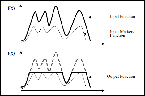
Figure 1: 1D example of the of the reconstruction by DILATION
Case Erosion
This case of use removes the dark points in a light image.
At each step the marker image is eroded by a structuring element of size 1. This algorithm is based on a recursive method whereby the maximum of the eroded image and the mask image is retained and used as the marker image at the next step. This operation is repeated until stability. The number of iterations depends on the input image and the marker image. As shown in the figure 2, the valleys are levelled up, which results in a much more homogeneous output image.
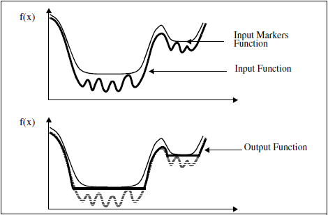
Figure 2: 1D example of the of the reconstruction by EROSION
This algorithm is used by the SoHExtremaProcessing engine.
SEE ALSO
SoHExtremaProcessing, SoMarkerBasedWatershedProcessing.
FILE FORMAT/DEFAULT
- GrayscaleResconstructionProcessing {
| computeMode | MODE_AUTO |
| neighborhood3d | CONNECTIVITY_26 |
| reconstructMode | EROSION |
| inMaskImage | NULL |
| inMarkerImage | NULL |
Library references: dualreconstruct numreconstruct
Member Enumeration Documentation
Constructor & Destructor Documentation
| SoGrayscaleResconstructionProcessing::SoGrayscaleResconstructionProcessing | ( | ) |
Constructor.
Member Data Documentation
Select the compute Mode (2D or 3D or AUTO) Use enum ComputeMode.
Default is MODE_AUTO
The input grayscale marker image containing seeds for reconstruction.
Default value is NULL. Supported types include: grayscale binary label image.
The input grayscale mask image constraining reconstruction.
Default value is NULL. Supported types include: grayscale binary label image.
In 3D configuration (see computeMode), the neighborhood connectivity defines the connectivity considered for processing adjacent voxels.
Use enum Neighborhood3d. Default is CONNECTIVITY_26.
| SoImageVizEngineOutput<SoSFImageDataAdapter,SoImageDataAdapter*> SoGrayscaleResconstructionProcessing::outImage |
The output image.
Default value is NULL. Supported types include: grayscale binary label color image.
Select the reconstruction mode to use.
Use enum ReconstructMode. Default is EROSION
The documentation for this class was generated from the following file:
- ImageViz/Engines/MathematicalMorphology/GeodesicTransformations/SoGrayscaleResconstructionProcessing.h