SoShapeHints Class Reference
[Properties]
Node that provides hints about shapes. More...
#include <Inventor/nodes/SoShapeHints.h>
Public Types | |
| enum | VertexOrdering { UNKNOWN_ORDERING = SoShapeHintsElement::UNKNOWN_ORDERING, CLOCKWISE = SoShapeHintsElement::CLOCKWISE, COUNTERCLOCKWISE = SoShapeHintsElement::COUNTERCLOCKWISE } |
| enum | ShapeType { UNKNOWN_SHAPE_TYPE = SoShapeHintsElement::UNKNOWN_SHAPE_TYPE, SOLID = SoShapeHintsElement::SOLID } |
| enum | FaceType { UNKNOWN_FACE_TYPE = SoShapeHintsElement::UNKNOWN_FACE_TYPE, CONVEX = SoShapeHintsElement::CONVEX } |
| enum | WindingType { NO_WINDING_TYPE = SoShapeHintsElement::NO_WINDING_TYPE, ODD_TYPE = SoShapeHintsElement::ODD_TYPE, NON_ZERO_TYPE = SoShapeHintsElement::NON_ZERO_TYPE, POSITIVE_TYPE = SoShapeHintsElement::POSITIVE_TYPE, NEGATIVE_TYPE = SoShapeHintsElement::NEGATIVE_TYPE, ABS_GEQ_TWO_TYPE = SoShapeHintsElement::ABS_GEQ_TWO_TYPE } |
Public Member Functions | |
| virtual SoType | getTypeId () const |
| SoShapeHints () | |
| virtual void | setOverride (const SbBool state) |
| virtual SbBool | isOverride () const |
Static Public Member Functions | |
| static SoType | getClassTypeId () |
| static SbBool | isVBOSupported () |
Public Attributes | |
| SoSFEnum | vertexOrdering |
| SoSFEnum | shapeType |
| SoSFEnum | faceType |
| SoSFEnum | windingType |
| SoSFBool | useVBO |
| SoSFFloat | creaseAngle |
| SoSFFloat | neighborTolerance |
Detailed Description
Node that provides hints about shapes.
By default, Open Inventor assumes very little about the shapes it renders. You can use the SoShapeHints node to indicate that vertex-based shapes (those derived from SoVertexShape) are solid, contain ordered vertices, or contain convex faces. For fastest rendering, specify SOLID, COUNTERCLOCKWISE, CONVEX shapes.
These hints allow Open Inventor to optimize certain rendering features. Optimizations that may be performed include enabling back-face culling and disabling two-sided lighting. For example, if an object is solid and has ordered vertices, Open Inventor turns on backface culling and turns off two-sided lighting. If the object is not solid but has ordered vertices, it turns off backface culling and turns on two-sided lighting. In all other cases, both backface culling and two-sided lighting are off.
Summary:
- Two-sided lighting: enabled if not solid and has ordered vertices.
Set vertexOrdering to COUNTERCLOCKWISE (usually) or CLOCKWISE.
- Backface culling: enabled if solid and has ordered vertices.
Set shapeType to SOLID.
Note: Two-sided lighting is automatically enabled for VolumeViz "slice" primitives, such as SoOrthoSlice and SoVolumeSkin.
This node allows the creation of polygons with holes. See the windingType field description, SoIndexedFaceSet, and SoFaceSet for details.
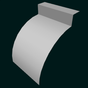
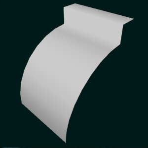
The SoShapeHints node also affects how default normals are generated. When a node derived from SoVertexShape has to generate default normals, it uses the creaseAngle field to determine which edges should be smooth-shaded and which ones should have a sharp crease. The crease angle is the angle between surface normals on adjacent polygons. For example, a crease angle of .5 radians means that an edge between two adjacent polygonal faces will be smooth shaded if the normals to the two faces form an angle that is less than .5 radians (about 30 degrees). Otherwise, it will be faceted.
-
creaseAngle = 0 creaseAngle = 0.5 creaseAngle = PI 
Smooth shaded means that the normal vectors of all the faces that share a vertex are averaged together to compute the normal vector for that vertex.
-
Normal averaging 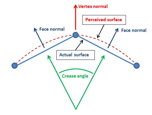
Normal generation is fastest when the creaseAngle is 0 (the default), producing one normal per facet. However, if a vertex is shared by two (or more) faces that should be faceted, the result of normal generation will be multiple normal vectors (one for each face) associated with that vertex. This is in conflict with using OpenGL Vertex Buffer Objects (VBO), which usually provide the best performance. VBO rendering only allows per-vertex (not per-face) normal vectors and only one normal vector per vertex. Some high-level shapes, like SoIndexedFaceSet, will automatically reorganize the geometry data to produce the requested appearance and still use VBOs for rendering. Lower level shapes like SoBufferedShape will ignore the creaseAngle field and compute normals using a crease angle of Pi in order to use VBOs for rendering. A creaseAngle of Pi produces one averaged normal per vertex.
See SoVertexShape for more information about Vertex Buffer Objects and shape rendering.
FILE FORMAT/DEFAULT
- ShapeHints {
| vertexOrdering | UNKNOWN_ORDERING |
| shapeType | UNKNOWN_SHAPE_TYPE |
| faceType | CONVEX |
| windingType | NO_WINDING_TYPE |
| creaseAngle | 0 |
| neighborTolerance | 1e-6 |
| useVBO | TRUE |
ACTION BEHAVIOR
- SoGLRenderAction, SoCallbackAction, SoRayPickAction, SoGetBoundingBoxAction
Sets the state to contain the hints; sets up optimizations based on the hints. Sets: SoShapeHintsElement, SoCreaseAngleElement, SoNeighborToleranceElement
SEE ALSO
SoVertexShape SoIndexedFaceSet SoFaceSet
- See related examples:
Member Enumeration Documentation
Hints about ordering of face vertices: if ordering of all vertices of all faces is known to be consistent when viewed from "outside" shape or not.
Winding type possible values.
- Enumerator:
Constructor & Destructor Documentation
| SoShapeHints::SoShapeHints | ( | ) |
Creates a shape hints node with default settings.
Member Function Documentation
| static SoType SoShapeHints::getClassTypeId | ( | ) | [static] |
Returns the type identifier for this class.
Reimplemented from SoNode.
| virtual SoType SoShapeHints::getTypeId | ( | ) | const [virtual] |
Returns the type identifier for this specific instance.
Reimplemented from SoNode.
| virtual SbBool SoShapeHints::isOverride | ( | ) | const [inline, virtual] |
Returns the state of the override field.
Reimplemented from SoNode.
| static SbBool SoShapeHints::isVBOSupported | ( | ) | [static] |
Indicates if Vertex Buffer Object (VBO) is supported by your graphics board.
| virtual void SoShapeHints::setOverride | ( | const SbBool | state | ) | [inline, virtual] |
Member Data Documentation
Indicates the minimum angle (in radians) between two adjacent face normals required to form a sharp crease at the edge when normal vectors are computed automatically by Open Inventor.
It has no effect when normal vectors are explicitly provided by the application.
Indicates whether each face is convex.
Because the penalty for non-convex faces is very steep (faces must be triangulated expensively), the default assumes all faces are convex. Therefore, shapes with concave faces may not be displayed correctly unless this hint is set to UNKNOWN_FACE_TYPE. Use enum FaceType. Default is CONVEX.
Specifies the tolerance value to use when default normals are computed.
The default is 1e-6.
Specifically it determines which (other) points in the shape are close enough to influence the normal at each vertex. Setting a smaller tolerance value will select a smaller number of points and can reduce the time required for computing normals on very large, very dense geometry.
If the OIV_NORMGEN_TOLERANCE environment variable is set, the default is 1/OIV_NORMGEN_TOLERANCE.
NOTE: field available since Open Inventor 8.0Indicates whether the shape is known to enclose a volume (SOLID) or not.
If the inside (the side away from the surface normal) of any part of the shape is visible, the shape is not solid. Use enum ShapeType. Default is UNKNOWN_SHAPE_TYPE.
This field controls whether subsequent shapes in the scene graph can use OpenGL Vertex Buffer Objects (VBO) to speed up rendering.
Default is TRUE (since Open Inventor 8.1). The default value can be set using the OIV_FORCE_USE_VBO environment variable (see SoPreferences).
In most cases there is no reason to set this field. Open Inventor will automatically choose the best rendering strategy. For example, VBOs generally provide the best performance for large shapes (many vertices), but not necessarily for small shapes. In specific cases it may be useful to influence these decisions using this field and/or the related environment variables including OIV_MIN_VERTEX_VBO and OIV_MIN_VERTEX_VAVBO_NOCACHE. See SoVertexShape for more discussion about shape rendering strategy.
NOTE: field available since Open Inventor 5.0Indicates how the vertices of faces are ordered.
CLOCKWISE ordering means that the vertices of each face form a clockwise loop around the face, when viewed from the outside (the side toward which the normal points). Use enum VertexOrdering. Default is UNKNOWN_ORDERING.
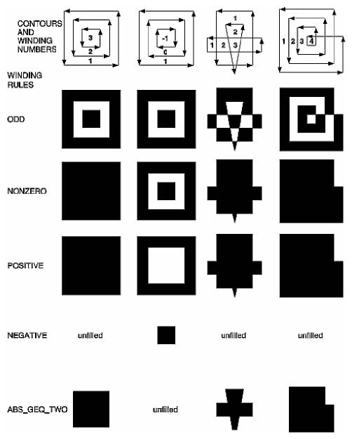
Indicates the winding rule used to define holes in a polygon.
It is used by SoIndexedFaceSet and SoFaceSet to determine which parts of the polygon are on the interior and which are on the exterior and should not be filled. By default this field value is NO_WINDING_TYPE, that is, no winding rules are used, so there are no holes. Use enum WindingType.
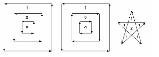
For a single contour, the winding number of a point is the signed number of revolutions we make around that point while traveling once around the contour (where a counterclockwise revolution is positive and a clockwise revolution is negative). When there are several contours, the individual winding numbers are summed. This procedure associates a signed integer value with each point in the plane. Note that the winding number is the same for all points in a single region.
The following figure shows three sets of contours and winding numbers for points inside those contours. In the left set, all three contours are counterclockwise, so each nested interior region adds one to the winding number. For the middle set, the two interior contours are drawn clockwise, so the winding number decreases and actually becomes negative.
|
|
NOTE: In LINES drawing style (see SoDrawStyle), if windingType is not NO_WINDING_TYPE, or if faceType is UNKNOWN_FACE_TYPE, the edges of the tessellated triangles will be drawn.
NOTE: field available since Open Inventor 4.0The documentation for this class was generated from the following file:
- Inventor/nodes/SoShapeHints.h