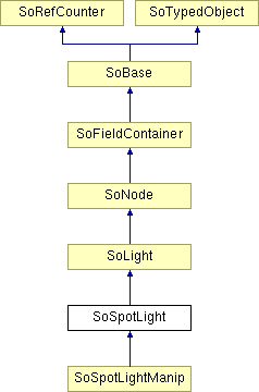
SoSpotLight Class Reference
[Lights & colors]
Node representing a spotlight source. More...
#include <Inventor/nodes/SoSpotLight.h>

Public Member Functions | |
| virtual SoType | getTypeId () const |
| SoSpotLight () | |
Static Public Member Functions | |
| static SoType | getClassTypeId () |
Public Attributes | |
| SoSFVec3f | location |
| SoSFVec3f | direction |
| SoSFFloat | dropOffRate |
| SoSFFloat | cutOffAngle |
Detailed Description
Node representing a spotlight source.
This node defines a spotlight style light source. A spotlight is placed at a fixed location in 3-space and illuminates in a cone along a particular direction. The intensity of the illumination drops off exponentially as a ray of light diverges from this direction toward the edges of the cone. The rate of drop-off and the angle of the cone are controlled by the dropOffRate and cutOffAngle fields.
A light node defines an illumination source that may affect subsequent shapes in the scene graph, depending on the current lighting model. Light sources are affected by the current transformation. A light node under an SoSeparator does not affect any objects outside that separator. Lights may be grouped under an SoGroup node and still affect the rest of the scene graph. The viewer classes automatically create a directional light, called the headlight, that is automatically updated to shine in the same direction the camera is pointed.
You can also use a node kit to create a light. See the reference page for SoLightKit.
The lighting model can be changed using an SoLightModel node. Effectively lighting is enabled by default (default model is PER_VERTEX_PHONG), but can be turned off by setting the lighting model to BASE_COLOR. In this case the object's diffuse color is used without modification. This can be useful for axes and annotations.
An SoEnvironment node can be used to specify additional options related to lighting:
- The ambient light component of the Phong reflection model.
- Light attenuation for SoPointLight and SoSpotLight nodes.
- Ambient occlusion.
When lighting is enabled, the appearance of most geometry depends on the normal vectors specified (or computed) for the geometry. See SoShapeHints for a discussion of normal computation and the concept of "crease angle". By default lighting is only computed for the "front" face of most geometry (there are some exceptions like SoOrthoSlice). Which face is the front depends on the vertex ordering. Also see SoShapeHints to control vertex ordering and to enable "two sided" lighting. Lighting of line geometry is affected by the tangent values, if any, specified with SoVertexProperty.
The color components specified for lights mean something different than for materials. For a light, the numbers correspond to a percentage of full intensity for each color. If the R, G, and B values for a light's color are all 1.0, the light is the brightest possible white. If the values are 0.5, the color is still white, but only at half intensity, so it appears gray. If R=G=1 and B=0 (full red and green with no blue), the light appears yellow. The intensity can also be modulated using the intensity field.
For materials, the numbers correspond to the reflected percentages of those colors. So if R=1, G=0.5, and B=0 for a material, that material reflects all the incoming red light, half the incoming green, and none of the incoming blue light. In other words, if an OpenGL light has components (LR, LG, LB), and a material has corresponding components (MR, MG, MB), then, ignoring all other reflectivity effects, the light that arrives at the eye is given by (LR*MR, LG*MG, LB*MB). As a result, for example, shining a pure blue light on a pure red cone has no visible effect.
Similarly, if you have two lights that send (R1, G1, B1) and (R2, G2, B2) to the eye, the components are added, giving (R1+R2, G1+G2, B1+B2). If any of the sums are greater than 1 (corresponding to a color brighter than the hardware can display), the component is clamped to 1.
The maximum number of lights depends on the hardware, but at least eight simultaneous lights are supported.
Note:
By default lighting is only computed at the vertices of the geometry and the resulting colors are interpolated across the geometry. As a result, the illumination cone of a spotlight may not be visible unless the geometry is highly tesselated.
FILE FORMAT/DEFAULT
- SpotLight {
| on | TRUE |
| intensity | 1 |
| color | 1 1 1 |
| location | 0 0 1 |
| direction | 0 0 -1 |
| dropOffRate | 0 |
| cutOffAngle | 0.785398 |
ACTION BEHAVIOR
- SoGLRenderAction
Activates this light (if so specified) during traversal. All shape nodes that come after this light in the scene graph are illuminated by this light. The light's location is affected by the current transformation. Sets: SoLightElement, SoLightIdElement
SEE ALSO
SoDirectionalLight, SoPointLight, SoLightModel
Constructor & Destructor Documentation
| SoSpotLight::SoSpotLight | ( | ) |
Creates a spotlight source node with default settings.
Member Function Documentation
| static SoType SoSpotLight::getClassTypeId | ( | ) | [static] |
Returns the type identifier for this class.
Reimplemented from SoLight.
Reimplemented in SoSpotLightManip.
| virtual SoType SoSpotLight::getTypeId | ( | ) | const [virtual] |
Returns the type identifier for this specific instance.
Reimplemented from SoLight.
Reimplemented in SoSpotLightManip.
Member Data Documentation
Angle (in radians) outside of which intensity is zero, measured from the center axis of the cone to an edge.
Principal direction of illumination (center axis of cone).
Rate of intensity drop-off per change in angle from primary direction: 0 = constant intensity, 1 = very sharp drop-off.
Location of the source.
The documentation for this class was generated from the following file:
- Inventor/nodes/SoSpotLight.h