|
Open Inventor Release 2024.2.3
|
|

| |
|
Open Inventor Release 2024.2.3
|
|
|
| |
This section describes a number of important property classes, all of which are derived from SoNode :
An SoMaterial node includes the following fields:
| ambientColor (SoMFColor) | reflected color of an object in response to the ambient lighting in the scene. The default value for this field is [0.2, 0.2, 0.2]. |
| diffuseColor (SoMFColor) | an object's base color. The default value for this field is [0.8, 0.8, 0.8]. |
| specularColor (SoMFColor) | reflective quality of an object's highlights. The default value for this field is [0.0, 0.0, 0.0]. |
| emissiveColor (SoMFColor) | light produced by an object. The default value for this field is [0.0, 0.0, 0.0]. |
| shininess (SoMFFloat) | degree of shininess of an object's surface, ranging from 0.0 for a diffuse surface with no shininess to a maximum of 1.0 for a highly polished surface. The default value for this field is 0.2. |
| transparency (SoMFFloat) | degree of transparency of an object's surface, ranging from 0.0 for an opaque surface to 1.0 for a completely transparent surface. The default value for this field is 0.0. |
 The transparency type is specified in the render action (see Applying Actions).
An example of setting values in an SoMaterial node is the following:
C++ :
C# :
Java :
Since gold is opaque, you can use the default value of 0.0 for the transparency field.
SoBaseColor, another class derived from SoNode, replaces only the diffuse color field of the current material and has no effect on other material fields.
If you are changing only the diffuse color of an object, use an SoBaseColor node in place of an SoMaterial node. For example, to represent a complex terrain that uses many different diffuse colors, use one SoMaterial node for the ambient, specular, and emissive color values, and then use one SoBaseColor node with multiple values for the changing diffuse colors. The SoBaseColor class is also useful when the light model is BASE_COLOR (see the section called “Draw-Style Node”).
An SoDrawStyle node includes the following fields:
| style (SoSFEnum) | current drawing style. Values for this field are |
| SoDrawStyle::FILLED filled regions (default) SoDrawStyle::LINES nonfilled outlines SoDrawStyle::POINTS points SoDrawStyle::INVISIBLE not drawn at all | |
| pointSize (SoSFFloat) | (for POINTS style) radius of points, in printer's points. The default value is 0.0. A value of 0.0 indicates to use the fastest value for rendering, which is typically 1.0. If this value is not 0.0, the point size is scaled by the amount required to keep it a constant size, which depends on the pixels per inch of the viewport region. |
Draw-style LINES and POINTS look best with a BASE_COLOR lighting model.
| lineWidth (SoSFFloat) | (for LINES style) line width, in printer's points (1 inch = 72.27 printer's points). Values can range from 0.0 to 256.0. The default value is 0.0, which indicates to use the fastest value for rendering. |
| linePattern (SoSFUShort) | (for LINES style) current line-stipple pattern. Values can range from 0 (invisible) to 0xffff (solid). The default value is 0xffff. |
Drawing_Styles__FILLED,_LINES,_POINTS_ "Drawing Styles (FILLED, LINES, POINTS)" shows the same object rendered in different drawing styles.
An SoLightModel node includes the following field:
| model (SoSFEnum) | current lighting model applied to all subsequent shape nodes in the scene graph. The lighting model tells the shape node how to compute lighting calculations during rendering. Values for this field are as follows: |
| SoLightModel::BASE_COLOR ignores light sources and uses only the diffuse color and transparency of the current material. | |
| SoLightModel::PHONG uses the OpenGL Phong lighting model, which takes into account all light sources in the scene and the object's surface orientation with respect to the lights. This lighting model (the default) usually requires at least one light in the scene. (There may be emissive color and ambient lighting also.) |
 In Inventor, shading (such as Gouraud or flat) is dictated by the combination of the material specification of the object, the lighting model, and the normal bindings. A shading model is not explicitly specified.
Plate 4 and Plate 5 show the same scene with the different lighting models. (Plate 4 uses BASE_COLOR, and Plate 5 uses PHONG.)
SoMaterial and SoBaseColor can be used along with any drawing style and any lighting model. In some cases, however, some of the material attributes might be ignored. For example, if you specify BASE_COLOR for the SoLightModel model field, only the diffuse color and transparency of the current material are used. But what happens if you specify only a base color (with SoBaseColor) and subsequently select the Phong lighting model for SoLightModel ? In this case, Inventor uses the base color for the diffuse color and the default or current material element values for the other SoMaterial fields.
By default, the light model is PHONG. For UserGuide_Images to render correctly, you need to specify normals and light sources. If you want to see only colored objects, change the light model to BASE_COLOR and use SoBaseColor to specify only the base (diffuse) color.
You can use the SoEnvironment node to simulate various atmospheric effects such as fog, haze, pollution, and smoke. For general purposes, these atmospheric effects are grouped under the term fog. The difference between fog and haze, for example, is simply the color and density.
Specifically, the SoEnvironment node allows you to specify the color and intensity of the ambient lighting, the light attenuation for point lights and spotlights, and the type, color, and visibility factor for fog. Plate 6 shows the effects of an SoEnvironment node. This image uses a value of FOG for the fog type. The fogColor is (0.2, 0.2, 0.46).
An SoEnvironment node includes the following fields:
| ambientIntensity (SoSFFloat) | intensity of ambient light in the scene. This field is used with Phong lighting. |
| ambientColor (SoSFColor) | color of ambient light in the scene. This field is used with Phong lighting. |
| attenuation (SoSFVec3f) | defines how light drops off with distance from a light source. You can specify squared, linear, and constant attenuation coefficients with respect to the distance of the light from the object's surface. (The three components of the vector are the squared, linear, and constant coefficients, in that order.) This field is used with Phong lighting. |
| fogType (SoSFEnum) | type of fog. Values for this field are |
| SoEnvironment::NONE no fog (default) SoEnvironment::HAZE opacity of the fog increases linearly with the distance from the camera SoEnvironment::FOG opacity of the fog increases exponentially with the distance from the camera | |
| SoEnvironment::SMOKE increase in fog opacity is an exponential-squared increase with the distance from the camera | |
| fogColor (SoSFColor) | color of the fog. |
| fogVisibility (SoSFFloat) | the distance at which fog totally obscures the objects in the scene. For the default value (0.0), this distance is adjusted to equal the far plane of the camera. Otherwise, it is used as is. |
For realistic scenes, clear the window to the fog color before drawing the fogged objects (see the SoXtRenderArea::setBackgroundColor() method.)
By default, Inventor does not assume anything about how the vertices in a vertex shape are ordered, whether its surface is closed or open, or whether the faces of the shape are convex or concave. If you know that the vertices are in a consistent order, that the shape is closed, or that the shape faces are convex, you can use the SoShapeHints node to notify Inventor so that it can optimize certain rendering features.
The SoShapeHints node has four fields:
| vertexOrdering (SoSFEnum) | provides hints about the ordering of the faces of a vertex-based shape derived from SoVertexShape. This field describes the ordering of all the vertices of all the faces of the shape when it is viewed from the outside. |
| Values for this field are | |
| SoShapeHints::UNKNOWN_ORDERING the ordering of the vertices is not known (the default) SoShapeHints::CLOCKWISE the vertices for each face are specified in clockwise order SoShapeHints::COUNTERCLOCKWISE the vertices for each face are specified in counterclockwise order | |
| shapeType (SoSFEnum) | SoShapeHints::UNKNOWN_SHAPE_TYPE the shape type is not known (the default) SoShapeHints::SOLID the shape is a solid object (not an open surface) |
| faceType (SoSFEnum) | SoShapeHints::UNKNOWN_FACE_TYPE the face type is not known SoShapeHints::CONVEX all faces of the shape are convex (the default) |
| creaseAngle (SoSFFloat) | used for automatic normal generation. See the section called “Generating Normals Automatically” |
If the shapeType is SOLID and the vertexOrdering is either CLOCKWISE or COUNTERCLOCKWISE, Inventor turns on backface culling and turns off two-sided lighting. If the shapeType is not SOLID and the vertexOrdering is either CLOCKWISE or COUNTERCLOCKWISE, Inventor turns off backface culling and turns on two-sided lighting. In all other cases, backface culling and two-sided lighting are both off. If you use the SoShapeHints node, be sure to describe the object accurately; otherwise, objects may be rendered incorrectly.
In general, the more information you specify with the shape-hints node, the faster the rendering speed. The exception to this rule is when shapeType is not SOLID and the vertexOrdering is either CLOCKWISE or COUNTERCLOCKWISE. In this case, rendering may be slower because two-sided lighting is automatically turned on and backface culling is turned off.
Use the SoComplexity node to indicate the amount of subdivision into polygons for subsequent shape nodes in the scene graph. This node has three fields:
| type (SoSFEnum) | general type of complexity. Values for this field are |
| SoComplexity::OBJECT_SPACE (the default) bases the subdivision on the object itself, regardless of where it is on the screen or which parts are closer to the viewer. SoComplexity::SCREEN_SPACE bases the complexity on the amount of screen space occupied by the object. Objects requiring the full screen require more detail; small objects require less detail. The result is that objects that are closer to the viewer usually receive more detail than objects that are farther away. This type of complexity is more expensive to compute than the others. In addition, it invalidates the render cache when the camera moves (see the discussion of render caching in Applying Actions). SoComplexity::BOUNDING_BOX renders a bounding box in place of the shape. This type is used for speed, when exact shapes are not required. It uses the current drawing style to render the box. | |
| value (SoSFFloat) | a value that provides a hint about the amount of subdivision desired, where 0.0 is minimum complexity and 1.0 is maximum complexity. The default is 0.5. |
| textureQuality (SoSFFloat) | a value that provides a hint about the quality of texture mapping used on the object. The trade-off is between speed of rendering and quality of texturing. A value of 0.0 indicates maximum speed (possibly turning off texturing completely), and 1.0 indicates finest texture quality. The default is 0.5. |
Specifying Different Levels of Complexity (left: OBJECT_SPACE; right: SCREEN_SPACE) shows the same object with different levels of complexity. The spheres at the left use object-space complexity and a complexity value of .5. The spheres at the right use screen-space complexity and a complexity value of .06. The NURBS examples in Curves and Surfaces use the SoComplexity node.
Inventor lets you define your data in a variety of different units. It uses meters as its default units, but you can use the SoUnits node to specify a different unit of measurement. The units node acts like a scale node by scaling subsequent shapes into the specified units. SoUnits can adjust the amount it scales an object by checking to see if any other units have been defined. The units node adjusts the scale so that the previously defined units are no longer in effect.
The SoUnits node has one field:
| units (SoSFEnum) | defines the current unit of measurement to be applied to all subsequent shapes in the scene graph. Possible values are as follows: SoUnits::METERS SoUnits::CENTIMETERS SoUnits::MILLIMETERS SoUnits::MICROMETERS SoUnits::MICRONS SoUnits::NANOMETERS SoUnits::ANGSTROMS SoUnits::KILOMETERS SoUnits::FEET SoUnits::INCHES SoUnits::POINTS SoUnits::YARDS SoUnits::MILES SoUnits::NAUTICAL_MILES |
To render your data in units other than these, use an SoUnits node to set the current units back to meters, followed by a scale node that scales from meters into the desired units.
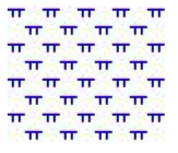
A pattern is a 32x32 bitmap that’s interpreted as a mask of 0s and 1s. Where a 1 appears, the corresponding pixel in the polygon is drawn; where a 0 appears, nothing is drawn. Using patterns is like using screen door transparency where you specify the pattern of the screen. OpenGL polygon stippling is used to render the pattern.
You can load a pattern file with method loadPatterns(). If the specified file name is not found, a default pattern will be used. If you specify only the file name without the path, the file will be loaded from the directory $OIVHOME/data/patterns/. If you want to specify your own path, give the path associated with the file name. (See method loadPatterns()).
You can load a pattern file containing one or more patterns using the loadPatterns() method or you can define and load patterns programmatically using the addPattern() method. It is possible to use this method before or without loadPatterns(). In this case, you must define a pattern buffer as shown below:
C++ :
C# :
Java :
This is an array of 128 bytes.
If you do not use either of these two methods, the default pattern will be used. Likewise, if you set the name or category fields with a bad name or category, the default pattern will be used.
Example : The file extension for a pattern file is .pat
In this figure, you can see a pattern file that defines two patterns in the “GEOLOGY” category.
Example : How to create a FaceSet filled with a pattern
C++ :
C# :
Java :