|
Open Inventor Release 2026.1.0
|
|

| |
|
Open Inventor Release 2026.1.0
|
|
|
| |
 Renders data volumes using direct volume rendering
More...
Renders data volumes using direct volume rendering
More...
#include <VolumeViz/nodes/SoVolumeRender.h>
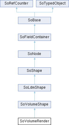
 Inheritance diagram for SoVolumeRender:
Public Member Functions | |
| virtual SoType | getTypeId () const |
| Returns the type identifier for this specific instance. | |
| SoVolumeRender () | |
| Constructor. | |
| void | setAbortCallback (SoVolumeRenderAbortCB *func, void *userData=NULL) |
| Sets callback to call during texture map rendering to test for an abort condition. | |
| Public Member Functions inherited from SoVolumeShape | |
| virtual void | setRenderProgress (SoProgressIndicator *ps) |
| Set an application defined SoProgressIndicator object which will raise an event before and after the rendering task, before and after each subtask (in this case: Texture creation and Geometry creation) and after each step in the subtasks which represents in most cases individual tiles of data. | |
| Public Member Functions inherited from SoShape | |
| virtual SbBool | affectsState () const |
| Overrides default method on SoNode. | |
| ShapeType | getShapeType () |
| Gets the current shape Full Scene Antialiasing type. | |
| Public Member Functions inherited from SoNode | |
| virtual void | setOverride (const SbBool state) |
| Turns the override flag on or off. | |
| virtual SbBool | isOverride () const |
| Returns the state of the override flag. | |
| virtual SoNode * | copy (SbBool copyConnections=FALSE) const |
| Creates and returns an exact copy of the node. | |
| virtual void | touch () |
| Marks an instance as modified, simulating a change to it. | |
| Public Member Functions inherited from SoFieldContainer | |
| void | setToDefaults () |
| Sets all fields in this object to their default values. | |
| SbBool | hasDefaultValues () const |
| Returns TRUE if all of the object's fields have their default values. | |
| SbBool | fieldsAreEqual (const SoFieldContainer *fc) const |
| Returns TRUE if this object's fields are exactly equal to fc's fields. | |
| void | copyFieldValues (const SoFieldContainer *fc, SbBool copyConnections=FALSE) |
| Copies the contents of fc's fields into this object's fields. | |
| SoNONUNICODE SbBool | set (const char *fieldDataString) |
| Sets one or more fields in this object to the values specified in the given string, which should be a string in the Open Inventor file format. | |
| SbBool | set (const SbString &fieldDataString) |
| Sets one or more fields in this object to the values specified in the given string, which should be a string in the Open Inventor file format. | |
| void | get (SbString &fieldDataString) |
| Returns the values of the fields of this object in the Open Inventor ASCII file format in the given string. | |
| virtual int | getFields (SoFieldList &list) const |
| Appends references to all of this object's fields to resultList, and returns the number of fields appended. | |
| virtual int | getAllFields (SoFieldList &list) const |
| Returns a list of fields, including the eventIn's and eventOut's. | |
| virtual SoField * | getField (const SbName &fieldName) const |
| Returns a the field of this object whose name is fieldName. | |
| virtual SoField * | getEventIn (const SbName &fieldName) const |
| Returns a the eventIn with the given name. | |
| virtual SoField * | getEventOut (const SbName &fieldName) const |
| Returns the eventOut with the given name. | |
| SbBool | getFieldName (const SoField *field, SbName &fieldName) const |
| Returns the name of the given field in the fieldName argument. | |
| SbBool | enableNotify (SbBool flag) |
| Notification at this Field Container is enabled (if flag == TRUE) or disabled (if flag == FALSE). | |
| SbBool | isNotifyEnabled () const |
| Notification is the process of telling interested objects that this object has changed. | |
| virtual void | setUserData (void *data) |
| Sets application data. | |
| void * | getUserData (void) const |
| Gets user application data. | |
| Public Member Functions inherited from SoBase | |
| virtual SbName | getName () const |
| Returns the name of an instance. | |
| virtual void | setName (const SbName &name) |
| Sets the name of an instance. | |
| void | setSynchronizable (const bool b) |
| Sets this to be a ScaleViz synchronizable object. | |
| bool | isSynchronizable () const |
| Gets the ScaleViz synchronizable state of this object. | |
| Public Member Functions inherited from SoRefCounter | |
| void | ref () const |
| Adds a reference to an instance. | |
| void | unref () const |
| Removes a reference from an instance. | |
| void | unrefNoDelete () const |
| unrefNoDelete() should be called when it is desired to decrement the reference count, but not delete the instance if this brings the reference count to zero. | |
| int | getRefCount () const |
| Returns current reference count. | |
| void | lock () const |
| lock this instance. | |
| void | unlock () const |
| unlock this instance. | |
| Public Member Functions inherited from SoTypedObject | |
| SbBool | isOfType (const SoType &type) const |
| Returns TRUE if this object is of the type specified in type or is derived from that type. | |
| template<typename TypedObjectClass> | |
| SbBool | isOfType () const |
| Returns TRUE if this object is of the type of class TypedObjectClass or is derived from that class. | |
Static Public Member Functions | |
| static SoType | getClassTypeId () |
| Returns the type identifier for this class. | |
| Static Public Member Functions inherited from SoVolumeShape | |
| static SoType | getClassTypeId () |
| Returns the type identifier for this class. | |
| Static Public Member Functions inherited from SoLdmShape | |
| static SoType | getClassTypeId () |
| Returns the type identifier for this class. | |
| Static Public Member Functions inherited from SoShape | |
| static SoType | getClassTypeId () |
| Returns the type identifier for this class. | |
| static SbBool | isPrimitiveRestartAvailable (SoState *state=NULL) |
| Returns TRUE if the primitive restart feature is available. | |
| Static Public Member Functions inherited from SoNode | |
| static SoType | getClassTypeId () |
| Returns the type identifier for this class. | |
| static SoNode * | getByName (const SbName &name) |
| A node's name can be set using SoBase::setName(). | |
| static int | getByName (const SbName &name, SoNodeList &list) |
| A node's name can be set using SoBase::setName(). | |
| Static Public Member Functions inherited from SoFieldContainer | |
| static SoType | getClassTypeId () |
| Returns the type of this class. | |
| Static Public Member Functions inherited from SoBase | |
| static SoType | getClassTypeId () |
| Returns type identifier for this class. | |
| Static Public Member Functions inherited from SoTypedObject | |
| static SoType | getClassTypeId () |
| Returns the type identifier for this class. | |
Public Attributes | |
| SoMFInt32 | dataSetIds |
| Specifies the list of volumes on which volume rendering is applied. | |
| SoSFEnum | numSlicesControl |
| Controls how the number of samples along each ray is determined. | |
| SoSFInt32 | numSlices |
| Specifies the number of samples along each ray. | |
| SoSFBitMask | lowResMode |
| Sets the method to use when moving in low resolution. | |
| SoSFInt32 | lowScreenResolutionScale |
| If lowResMode is DECREASE_SCREEN_RESOLUTION, render the volume at a lower screen resolution. | |
| SoSFBool | subdivideTile |
| If true, LDM tiles will be subdivided for rendering. | |
| SoSFBool | fixedNumSlicesInRoi |
| When this field is set to FALSE (the default), the number of samples set by numSlices is the number of samples used for the region defined by the current ROI. | |
| SoSFInt32 | projectedTileSubdivision |
| When doing volume projection (see SoProjection), only the geometry (corner vertices) of the LDM tiles are projected, not the individual voxels. | |
| SoSFBool | opacityCorrection |
| Controls whether opacity correction is done. | |
| SoSFEnum | renderMode |
| Specifies how the voxels along each sampling ray are combined to form the final image. | |
| SoSFEnum | samplingAlignment |
| Specifies which technique to use to align rayCast samples. | |
| SoSFFloat | opacityThreshold |
| Specifies a threshold opacity (alpha) value that defines voxels considered to be "solid" (non-transparent). | |
| SoSFVec2i32 | stillScreenTileSize |
| Specifies the size of the screen tiles used for rendering. | |
| Public Attributes inherited from SoVolumeShape | |
| SoSFEnum | interpolation |
| Interpolation mode. | |
| SoDEPRECATED SoSFEnum | composition |
| Specifies color composition mode. | |
| Public Attributes inherited from SoShape | |
| SoSFBool | boundingBoxIgnoring |
| Whether to ignore this node during bounding box traversal. | |
Friends | |
| class | SoVolumeRenderLdm |
| class | SoVolumeRenderRaycast |
Deprecated | |
| SoDEPRECATED SoSFBool | lighting |
| Indicates if lighting is required. | |
| SoDEPRECATED SoSFVec3f | lightDirection |
| Light direction (relative to the volume). | |
| SoDEPRECATED SoSFFloat | lightIntensity |
| Light intensity in the range [0-1]. | |
| SoDEPRECATED SoSFBool | viewAlignedSlices |
| Indicates if samples should be computed in a view-aligned manner. | |
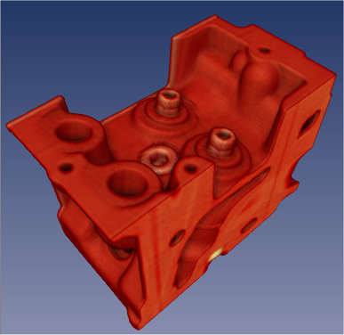
Renders data volumes using direct volume rendering
This node renders volume data using "direct volume rendering". The volume process involves sampling, interpolation, classification and composition. The rendering algorithm is a GPU-based technique called raycasting. Raycasting has similarities to the well known algorithm called raytracing, but is specialized for volume data (renders voxels not triangles) and does not currently implement reflection or refraction. One or more "rays" are cast through the volume from each relevant pixel on the screen. Samples are taken at intervals along each ray. The sample interval is controlled by the numSlices and numSlicesControl fields. At each sample point a value is interpolated from the closest voxels. The interpolation technique is controlled by the interpolation field. Classification means that color and opacity are computed based on the current SoDataRange and SoTransferFunction (and possibly values from other volumes - see SoVolumeShader). Optional rendering effects may modify the base color and/or opacity. These effects are controlled by an SoVolumeRenderingQuality node and include lighting, shadows, edge coloring, boundary opacity and more. The sample is then composited with other samples along the ray. Composition is controlled by the renderMode field. By default colors are combined based on the opacity of the sample (alpha blending). The ray is terminated if it reaches full opacity or reaches the current depth in the depth buffer.
The voxel's color to be combined during the composition step are retrieved in 2 different ways according the type of volume data:
The voxel's color is also combined with the current base color and transparency (see definition of base color here) set for example with an SoMaterial or an SoPhysicalMaterial node. This means that, for example, the current transparency can be used as a global alpha scale factor to decrease the opacity of all voxels.
If the light SoLightModel::model is either PER_VERTEX_PHONG or PER_PIXEL_PHONG, the final voxel's color is also affected by the fields emissiveColor, specularColor and shininess of the current SoMaterial. If the light SoLightModel::model is PHYSICALLY_BASED the final voxel's color is also affected by the fields specular roughness metallic of the current SoPhysicalMaterial.
The samplingAlignment field controls whether the samples are axis aligned (perpendicular to one axis of the volume), view aligned (perpendicular to the view direction) or boundary aligned (each ray starts at the first intersected voxel with alpha value > 0). Generally boundary aligned slices should be used (better image quality). Using SoVolumeGroup, SoVolumeIsoSurface or SoProjection nodes will automatically switch to view-aligned samples.
The property nodes SoVolumeIsoSurface and SoVolumeDataDrawStyle add additional rendering styles and can be used, for example, to force SoVolumeRender to draw a GPU computed isosurface instead of volume rendering.
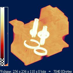
Example rendering:
| lighting = FALSE | lighting = TRUE |
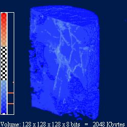 | 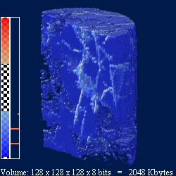 |
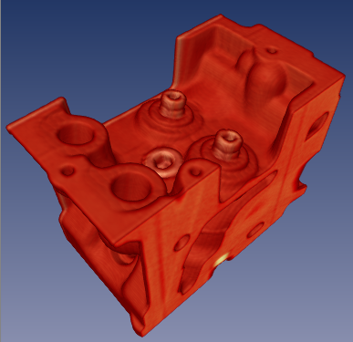
| composition = ALPHA_BLENDING | composition = MAX_INTENSITY |
 |  |
VolumeViz provides several mechanisms for combining or rendering multiple volumes, depending on the application's specific requirements. There are several cases:
Multiple independent volumes
These are volumes in the same scene that are completely independent (but might overlap in space) or have different dimensions or different extents. For example, medical datasets from different modalities.
In order to ensure that the rendering of overlapping transparent volumes is properly interleaved, there are 2 options:
The SoVolumeShader node allows a variety of custom shader functions to be defined for special computation or rendering effects on single volumes or multiple volumes. All of these features require programmable shader support on the GPU. Be sure to use an SoMultiDataSeparator (instead of SoSeparator) when combining multiple volumes.
It is possible to compose datasets that have different dimensions, tile sizes and transformations. In those cases, the volume rendering will be applied on the union of the extents of all the SoVolumeData nodes on state.
In addition, texture coordinates conversion functions are provided in the VolumeViz/vvizStructure.h* shader include in order to help fetch the correct data values in custom shaders.
For instance,
can be used to convert texture coordinates related to one dataset to texture coordinates related to another dataset.
The conversion is based solely on the transformations applied to each dataset, which are defined by their model matrix and their extent. Please note that the model matrix of a dataset is defined by to the SoTransformation nodes that are placed before the SoDataSet node in the order of the traversal.
See SoVolumeShader::FRAGMENT_COMPUTE_COLOR for an example of a shader implementing the VVizComputeFragmentColor() function in that case.
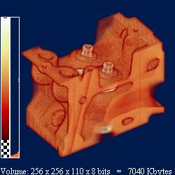
The SoVolumeRenderingQuality property node allows you to to enable GPU computed lighting based on the first SoLight node in the scene graph. (Note that this is typically the viewer's "headlight".) VolumeViz supports two lighting algorithms. They are both computed on the GPU and are independent (but normally only one should be enabled).
| Gradient lighting | Deferred lighting |
 | 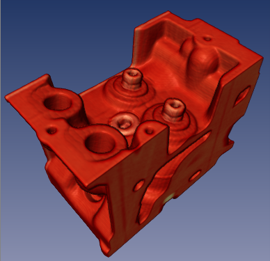 |
Open Inventor shadow rendering works for volume rendering similar to any other geometry. When shadow rendering is enabled (see SoShadowGroup), non-transparent voxels can cast and receive shadows (see SoShadowStyle). Shadow rendering is independent of whether lighting is enabled for the volume.
SoVolumeRender also supports "ambient occlusion" rendering (see the field SoVolumeRenderingQuality::ambientOcclusion). This rendering mode is visually a kind of self-shadowing and represents an approximation of the effect of ambient global lighting in the scene. Ambient occlusion can be combined with gradient or deferred lighting and with shadow casting.
| Shadow casting | Ambient occlusion |
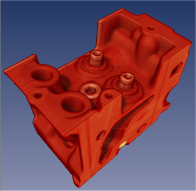 |  |
VolumeViz provides multiple tools for clipping volume rendering. Any or all of these tools may be combined for more complex clipping situations. Note that these tools clip all volume shapes including slices.
SoRayPickAction handles picking of VolumeViz shapes similar to other geometry in the scene, but with additional features. Picking on an SoVolumeRender node can return the first non-transparent voxel "hit" or the entire set of intersected voxels along the pick ray, depending on the pickAll flag of the SoRayPickAction. Similar to other geometry, SoPickedPoint can return a "detail" class specific to SoVolumeRender. SoVolumeRenderDetail returns the IJK (voxel coordinate) position of the pick and the data value at that point.
The SoVolumeRender node (by default) uses the GPU to compute the picked voxel during an SoRayPickAction. For this to work, the SoRayPickAction must have its scene manager initialised using the method SoAction::setSceneManager(). SoHandleEventAction does this automatically, so it is not necessary for the application to take any action when using (for example) an SoEventCallback node and calling the getPickedPoint() method. However if the application creates its own SoRayPickAction then it should set the scene manager. If no scene manager is specified, a warning message is issued and software picking is done. If necessary, using the GPU for volume picking may be disabled by setting the environment variable IVVR_GPU_PICKING to 0 (see SoPreferences).
The SoVolumeRender node supports projected volume rendering, for example rendering a volume defined on a grid of latitude / longitude coordinates. Projection is enabled by adding an SoProjection node before the SoVolumeRender node (see SoProjection for more information about supported coordinate systems, ellipsoids and map projections). The projection quality versus speed ratio can be controlled using the new projectedTileSubdivision field that defines how often each tile's geometry will be subdivided when projected. This is important because only the corner points of the tiles are projected, not the individual voxels. So subdividing the tiles provides a better approximation of the actual shape of the grid. Volume projection works with both regular (uniform voxel spacing) and rectilinear (non-uniform voxel spacing) grids. SoProjection automatically selects view-aligned sampling.
Warning:
Volume rendering performance is affected by many factors including the size of the volume and the rendering options selected. Image quality is also affected by many rendering options and, in general, higher quality implies lower performance. Some of the factors affecting volume rendering performance are:
Number of samples (slices):
This is controlled by the numSlices and numSlicesControl fields. Note that better image quality can obtained with the same number of samples by enabling options like preintegrated rendering (see SoVolumeRenderingQuality) and/or the BOUNDARY_ALIGNED setting for samplingAlignment. The number of samples can be automatically decreased when interacting using an SoInteractiveComplexity node.
We recommend to set the numSlicesControl field to AUTOMATIC and the numSlices field to -1. The number of samples will be computed based on the dimensions of the volume (number of voxels on each axis), the SoComplexity::value setting and the viewing direction. If the viewing direction changes, the number of samples will be automatically adjusted.
Opacity:
Increasing the number of opaque, or nearly opaque, voxels in the volume (using SoTransferFunction) will generally improve performance because the sampling rays can terminate sooner. See also IVVR_ALPHA_THRESHOLD_INTERACTIVE in SoPreferences.
If you are using a completely opaque transfer function, for example with a "volume probe", SoVolumeSkin will generate the same image much faster.
Tile size:
For backward compatibility, the default tile size is still only 64. This is quite small for modern CPU/GPU hardware. The smaller the tile size, the larger the total number of tiles that must be managed by VolumeViz. This overhead can be significant, especially for operations that require reloading the data textures on the GPU, for example, changing the data range (SoDataRange). For smaller volumes, like 512^3, it can be efficient to set the tile size large enough to contain the entire volume. For very large volumes, larger tile sizes are efficient for SoVolumeRender but somewhat inefficient for slice rendering because complete tiles must be loaded even though the slice only uses part of the data (see also SoSlice::largeSliceSupport). Applications should experiment.
For volumes stored in LDM file format, the tile size must be specified when the volume is converted to LDM (see SoConverter and the "-t" option). For other data data formats the tile size can be specified using the field SoVolumeData::ldmResourceParameters, but only after setting the field SoDataSet#filename or calling the setReader() method.
For simple data sets, a basic VolumeViz rendering could be achieved with only a few nodes: minimally an SoVolumeData node to identify the data set and one rendering node. However most data sets need at least some of the additional nodes shown here in order to get a correct and useful rendering. Most applications will need additional nodes to take advantage of region of interest, interaction, clipping and other VolumeViz features. Please consider the code shown here as simply a guideline and a starting point for exploring the many powerful features available in Open Inventor.
Note that some of the property nodes (data, material, color map, etc) will typically be shared by multiple rendering nodes. For example the volume data usually only needs to be loaded once, using a single SoVolumeData node. Multiple slices and/or regions can be rendered using that data node and they may use the same transfer function or each have their own.
Also note that this example is for a data volume, not a label volume. Please see the notes about label volumes following the code block.
A label volume, also known as a label field, is usually the result of doing some sort of segmentation on a data volume. Each voxel value is an integer label (id) identifying which material, object, etc that the voxel belongs to. There could be 100's or 1000's of labels, but there might be as few as 8 label values. For example, a simple label volume might have 7 opaque materials plus plus an "exterior" material which is completely transparent. Conceptually, there is one big difference between a (typical) data volume and a label volume. A data volume is conceptually a set of discrete samples taken from a continuous scalar field. So we know the exact value at the center of each voxel and interpolate between those values to get the value at any position in between voxels. In a label volume we normally consider each voxel to belong completely to one material, so the value is constant until we cross the boundary into the next voxel. Therefore we do not want to interpolate the label values.
When rendering a label volume, make the following changes to the above example:
If rendering isosurfaces (SoVolumeIsosurface), set the field SoVolumeRenderingQuality::segmentedInterpolation to TRUE.
It is also important to set the data range, texture precision and color map size carefully. Please see the label volume discussion in SoTransferFunction.
| interpolation | LINEAR |
| lighting | FALSE |
| lightDirection | -1, -1, -1 |
| lightIntensity | 1 |
| numSlices | 0 |
| numSlicesControl | AUTOMATIC |
| samplingAlignment | BOUNDARY_ALIGNED |
| lowResMode | DECREASE_NONE |
| lowScreenResolutionScale | 1 |
| subdivideTile | FALSE |
| projectedTileSubdivision | 1 |
| fixedNumSlicesInRoi | FALSE |
| opacityCorrection | TRUE |
| renderMode | VOLUME_RENDERING |
| dataSetIds | [] |
SoGetBoundingBoxAction
Computes the bounding box that encloses the volume.
SoRayPickAction
Picking always returns the first non-transparent voxel intersected by the pick ray. The old behavior can be restored by using an SoPickStyle node set to BOUNDING_BOX.
SoVolumeData, SoTransferFunction, SoROI, SoVolumeShader, SoVolumeIsosurface, SoVolumeRenderingQuality, SoProjection, SoVolumeRendering, SoUniformGridClipping, SoVolumeClippingGroup, SoInteractiveComplexity
Definition at line 759 of file SoVolumeRender.h.
| typedef AbortCode SoVolumeRender::SoVolumeRenderAbortCB(int totalElems, int thisElem, void *userData) |
Definition at line 1170 of file SoVolumeRender.h.
Abort code for callback.
| Enumerator | |
|---|---|
| CONTINUE | Continue rendering as usual. |
| ABORT | The render action of the SoVolumeRender node is aborted. The render action continues for the remaining part of the scene graph. |
| SKIP | The current slice is not drawn. Rendering continues with the next slice. |
Definition at line 1151 of file SoVolumeRender.h.
Method to use when moving in low resolution.
Used with lowResMode field.
| Enumerator | |
|---|---|
| DECREASE_NONE | No low resolution mode when moving. |
| DECREASE_SLICES | Decrease the number of samples according to SoComplexity::value when moving. It has no effect if numSlicesControl is set to AUTOMATIC because this mode always uses the SoComplexity node to compute the number of samples to draw. |
| DECREASE_SCREEN_RESOLUTION | Downscale the screen resolution of the volume when moving by the factor defined in lowScreenResolutionScale. |
Definition at line 767 of file SoVolumeRender.h.
Number of samples control mode.
Used with numSlicesControl field.
| Enumerator | |
|---|---|
| ALL | Use all samples. The number of samples depends on the viewing direction. |
| MANUAL | Use the number of samples specified by the numSlices field. The number of samples does not depend on the viewing direction. |
| AUTOMATIC | (Recommended) Use a number of samples computed as follows: The number of samples does not depend on the viewing direction. If numSlices is any value less than or equal to 0, the dimension of the volume data is used instead of numSlices, so The factor 2 is used because by default complexity is equal to 0.5. So, by default, the behavior for numSlices greater than zero is the same as MANUAL and the default behavior for numSlices less than or equal to zero is the same as ALL. |
| MAIN_AXIS | Use a number of samples computed as follows: The number of samples depends on the viewing direction. |
Definition at line 789 of file SoVolumeRender.h.
Composition mode.
Used with the renderMode field.
NOTE: enumeration value available since Open Inventor 9.1
| Enumerator | |
|---|---|
| VOLUME_RENDERING | Alpha compositing (Default). Also called Direct Volume Rendering (DVR) it blends the R, G, and B components for each data value along the sampling ray based on the alpha value (alpha blending). |
| MIN_INTENSITY_PROJECTION | Minimum intensity projection (MinIP). The minimum value found along each ray is used to determine color. |
| MAX_INTENSITY_PROJECTION | Maximum intensity projection (MIP). The maximum value found along each ray is used to determine color. |
| SUM_INTENSITY_PROJECTION | Ray sum intensity projection (RSP). The values found along each ray are accumulated. Then the total value is normalized by the nominal number of samples for every ray (see numSlices), which is the same for all rays. The values seen in shader functions, e.g. VVizComputeFragmentColor are still in the range 0..1, but the range of values that represents is quite different from the voxel data range. |
| AVERAGE_INTENSITY_PROJECTION | Average Intensity projection (AIP). The values found along each ray are accumulated. The total value is divided by the actual number of samples along the current ray. The actual number of samples may be different for each ray. The resulting data range will be similar to the voxel data range but not necessarily the same. If there are many low, e.g. 0, valued voxels, the average may be very small. |
| MAX_INTENSITY_DIFFERENCE_ACCUMULATION | Maximum Intensity Difference Accumulation (MIDA). Assuming the important features of the volumetric datasets are of high scalar values, this mode changes the compositing behavior by decreasing the accumulated color and opacity when the incoming sample's scalar intensity is higher than any of those before it along the viewing ray. In this way, the high scalar value features in the volumetric datasets won't be occluded as much as in a standard compositing (i.e. VOLUME_RENDERING). See Instant volume visualization using maximum intensity difference accumulation. Stefan Bruckner and M. Eduard Groller. 2009. In Proceedings of the 11th Eurographics / IEEE - VGTC conference on Visualization (EuroVis'09) for details. |
| INTENSITY_DIFFERENCE_ACCUMULATION | Intensity Difference Accumulation. This mode acts as MIDA but only the opacity of the accumulated color is affected and the modulation is based on the intensity difference of two consecutive samples. This mode should emphase the difference between two different structures with different scalar intensities. See Fast Volumetric Data Exploration with Importance-Based Accumulated Transparency Modulation. Wan Yong and Hansen Chuck, 2010, IEEE/ EG Symposium on Volume Graphics for details. |
| MAX_GRADIENT_DIFFERENCE_ACCUMULATION | Maximum Gradient Difference Accumulation. This mode acts as INTENSITY_DIFFERENCE_ACCUMULATION but the composition is affected when the incoming sample's gradient is higher than any of those before it along the viewing ray. It aims at revealing important features (i.e. higher gradient transitions) all along the ray direction. |
| GRADIENT_DIFFERENCE_ACCUMULATION | Gradient Difference Accumulation. This mode acts as MAX_GRADIENT_DIFFERENCE_ACCUMULATION but the opacity modulation is based on the gradient difference of two consecutive samples. It leads to a more transparent result, as more samples along the viewing ray contribute to the final result. |
Definition at line 982 of file SoVolumeRender.h.
Sampling alignment.
Used with the samplingAlignment field. NOTE: enumeration value available since Open Inventor 9.1
| Enumerator | |
|---|---|
| VIEW_ALIGNED | Samples are located on planes perpendicular to the view direction. |
| DATA_ALIGNED | Samples are located on planes perpendicular to one axis of the volume. |
| BOUNDARY_ALIGNED | Samples are located on shells aligned with the volume's internal "boundary". Each ray begins sampling at the first intersected voxel that has an alpha value > opacityThreshold. |
| SMOOTH_BOUNDARY_ALIGNED | Similar to BOUNDARY_ALIGNED but uses a cubic interpolation to compute the boundary, giving smoother results when using SoVolumeRenderingQuality::deferredLighting. When using linear interpolation and deferred lighting, BOUNDARY_ALIGNED can generate "flat shading" due to linear interpolation between voxels. SMOOTH_BOUNDARY_ALIGNED will generate a smooth shading using a cubic interpolation to find the volume's boundary and use a linear interpolation for the rest of volume. This is a good compromise between result and performances of a full tricubic interpolation. Please refer to SoVolumeRenderingQuality::deferredLighting and SoVolumeShape::interpolation for details. LIMITATIONS SMOOTH_BOUNDARY_ALIGNED is not supported in the following case:
|
Definition at line 1061 of file SoVolumeRender.h.
| SoVolumeRender::SoVolumeRender | ( | ) |
Constructor.
|
static |
Returns the type identifier for this class.
|
virtual |
Returns the type identifier for this specific instance.
Reimplemented from SoVolumeShape.
| void SoVolumeRender::setAbortCallback | ( | SoVolumeRenderAbortCB * | func, |
| void * | userData = NULL ) |
Sets callback to call during texture map rendering to test for an abort condition.
When not in raycasting mode, it will be called for each element that is rendered.
In the case of LDM, an element is a tile, totalElems is the number of tiles that will be drawn, and thisElem is the number (counting from one) of the next tile to be drawn. The quotient thisElem / totalElems represents the progress of the volume rendering process.
In the non-LDM case, an element is a slice, totalElems is the number of slices that will be drawn, and thisElem is the number (counting from one) of the next slice to be drawn. The quotient thisElem / totalElems represents the progress of the volume rendering process.
This allows applications to terminate rendering of this node prematurely if some condition occurs. It does not terminate traversal of the scene graph. (For that use the SoGLRenderAction abort callback.) The callback function should return one of the AbortCode codes to indicate whether rendering should continue.
|
friend |
Definition at line 1475 of file SoVolumeRender.h.
|
friend |
Definition at line 1476 of file SoVolumeRender.h.
| SoMFInt32 SoVolumeRender::dataSetIds |
Specifies the list of volumes on which volume rendering is applied.
This field specifies a list of datasets using their dataset id (see SoDataSet::dataSetId and SoDataSetId::id). It defines the geometry of the volume rendering as the union of the extents of each dataset specified in this list.
For example, when equal to [1, 2], volume rendering is applied on the union of the extents of the datasets of ids 1 and 2.
Notes:
Limitations: This field is ignored and only the last dataset on state is used for the volume rendering when:
The default value is an empty array.
NOTE: field available since Open Inventor 10.12.0
Definition at line 863 of file SoVolumeRender.h.
| SoSFBool SoVolumeRender::fixedNumSlicesInRoi |
When this field is set to FALSE (the default), the number of samples set by numSlices is the number of samples used for the region defined by the current ROI.
Therefore the number of samples may change when the ROI size changes. When TRUE, numSlices is the number of samples for the whole volume. In this case the sample density is constant, independent of the ROI size. Default is FALSE.
NOTE: field available since Open Inventor 7.1
Definition at line 946 of file SoVolumeRender.h.
| SoDEPRECATED SoSFVec3f SoVolumeRender::lightDirection |
Light direction (relative to the volume).
The default is (-1,-1,-1). Only affects CPU computed lighting (i.e. when the lighting field is TRUE).
Definition at line 1221 of file SoVolumeRender.h.
| SoDEPRECATED SoSFBool SoVolumeRender::lighting |
Indicates if lighting is required.
Default is FALSE.
NOTE: Better performance for lighting can be obtained using the SoVolumeRenderingQuality node. Using SoVolumeRenderingQuality, lighting is determined by the first light in the scene graph (similar to other geometry) and the lighting computation is done on the GPU (therefore SoVolumeRenderingQuality requires programmable shaders).
Using the lighting field, lighting is determined by the lightDirection field and the lighting computation is done on the CPU. This requires RGBA textures to be loaded on the GPU which uses more texture memory and requires more time to modify the transfer function (color map) because textures must be reloaded. Note that activating or deactivating lighting will also normally force the textures to be recreated, which may be slow.
NOTE: Only set the lighting field to TRUE in SoVolumeRenderingQuality or SoVolumeRender. Do not set both lighting fields to TRUE.
Definition at line 1214 of file SoVolumeRender.h.
| SoDEPRECATED SoSFFloat SoVolumeRender::lightIntensity |
Light intensity in the range [0-1].
The default is 1. Only affects CPU computed lighting (i.e. when the lighting field is TRUE).
Definition at line 1228 of file SoVolumeRender.h.
| SoSFBitMask SoVolumeRender::lowResMode |
Sets the method to use when moving in low resolution.
Use enum LowResMode. Default is DECREASE_NONE.
Definition at line 906 of file SoVolumeRender.h.
| SoSFInt32 SoVolumeRender::lowScreenResolutionScale |
If lowResMode is DECREASE_SCREEN_RESOLUTION, render the volume at a lower screen resolution.
when moving. The resolution used is the current screen resolution divided by lowScreenResolutionScale. Default is 1. A value of 2 or 4 is recommended if using this option.
NOTE: field available since Open Inventor 7.0
Definition at line 915 of file SoVolumeRender.h.
| SoSFInt32 SoVolumeRender::numSlices |
Specifies the number of samples along each ray.
The default is -1, which means to use the volume dimensions (number of voxels on each axis) when the numSlicesControl field is set to AUTOMATIC.
NOTE: This value is not used if the numSlicesControl field is set to ALL (the default for that field).
Definition at line 887 of file SoVolumeRender.h.
| SoSFEnum SoVolumeRender::numSlicesControl |
Controls how the number of samples along each ray is determined.
Use enum NumSlicesControl. Default is AUTOMATIC. Generally increasing the number of samples will increase the image quality, but decrease the performance (frames per second).
We recommend to set the numSlicesControl field to AUTOMATIC and the numSlices field to 0. The number of samples will be computed based on the dimensions of the volume (number of voxels on each axis), the SoComplexity::value setting and the viewing direction. If the viewing direction changes, the number of samples will be automatically adjusted.
Definition at line 877 of file SoVolumeRender.h.
| SoSFBool SoVolumeRender::opacityCorrection |
Controls whether opacity correction is done.
If TRUE, opacity is automatically adjusted to give similar appearance no matter how many samples are used. If FALSE, opacity is not corrected and increasing the number of samples will increase the opacity. Default is TRUE.
Generally this field should always be set to true. NOTE: field available since Open Inventor 8.1
Definition at line 975 of file SoVolumeRender.h.
| SoSFFloat SoVolumeRender::opacityThreshold |
Specifies a threshold opacity (alpha) value that defines voxels considered to be "solid" (non-transparent).
Many volume data sets are composed of objects of interest floating in an approximately transparent "fog", depending on opacity values in the transfer function. Several effects like BOUNDARY_ALIGNED sampling, ambientOcclusion and deferredLighting need to locate the boundary between solid objects and ambient fog. This field defines a threshold in the range [0, 1]. Voxels are considered solid if their alpha value is greater than opacityThreshold.
A value of 0.0 generally works well with a transfer function containing "binary" opacity (a transfer function with only fully transparent or fully opaque colors). If this is not the case, you should set this value according to your visualization parameters. Generally between 0.1 and 0.5.
Default is 0.1, Ignore low visibility voxels.
NOTE: field available since Open Inventor 9.3
Definition at line 1136 of file SoVolumeRender.h.
| SoSFInt32 SoVolumeRender::projectedTileSubdivision |
When doing volume projection (see SoProjection), only the geometry (corner vertices) of the LDM tiles are projected, not the individual voxels.
This can produce an imprecise projected volume when using large LDM tiles or low resolution levels (where the LDM tiles are larger).
This field controls how many times the tile geometry will be subdivided (producing more vertices) before being projected. Subdivision gives a smoother, more accurage shape, but requires much more computational power and may reduce rendering performance. Default is 1 (subdivide once).
NOTE: This field is ignored in raycasting mode (the default).
NOTE: field available since Open Inventor 7.1
Definition at line 964 of file SoVolumeRender.h.
| SoSFEnum SoVolumeRender::renderMode |
Specifies how the voxels along each sampling ray are combined to form the final image.
Use enum RenderMode. Default is VOLUME_RENDERING (alpha blending).
NOTE: field available since Open Inventor 9.1
Definition at line 1055 of file SoVolumeRender.h.
| SoSFEnum SoVolumeRender::samplingAlignment |
Specifies which technique to use to align rayCast samples.
Use enum SamplingAlignment. Default is BOUNDARY_ALIGNED.
VIEW_ALIGNED: Samples are located on planes perpendicular to the view direction.
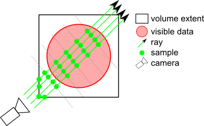
DATA_ALIGNED: Samples are located on planes perpendicular to one axis of the volume.
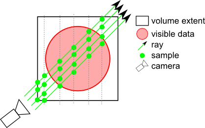
BOUNDARY_ALIGNED: Samples are located on shells aligned with the volume's internal "boundary". Each ray begins sampling at the first intersected voxel that has an alpha value > opacityThreshold. This technique greatly decreases "slicing" artifacts even with a relatively small number of slices. It is strongly recommended to enable this mode when using SoVolumeRenderingQuality::ambientOcclusion.
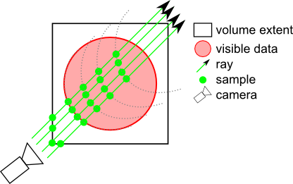
SMOOTH_BOUNDARY_ALIGNED: Similar to BOUNDARY_ALIGNED but uses a cubic interpolation to compute the boundary, giving smoother results when using SoVolumeRenderingQuality::deferredLighting.
NOTE: If an SoVolumeGroup or SoProjection node applies to this node, the field is ignored and VIEW_ALIGNED is used.
NOTE: field available since Open Inventor 9.1
Definition at line 1118 of file SoVolumeRender.h.
| SoSFVec2i32 SoVolumeRender::stillScreenTileSize |
Specifies the size of the screen tiles used for rendering.
Default is (-1, -1), it means no screen tiling rendering.
Definition at line 1141 of file SoVolumeRender.h.
| SoSFBool SoVolumeRender::subdivideTile |
If true, LDM tiles will be subdivided for rendering.
Fully transparent sub-tiles won't be rendered, thus (potentially) increasing the speed of the rendering if an expensive shader is being used and significant regions of the volume are fully transparent. However using false is faster if the user will frequently change the data range (e.g. window center/width in medical applications). SubTileDimension can be changed using SoVolumeData node's ldmResourceParameters field. Default is FALSE.
See the 'subtileDimension' field in SoLDMResourceParameters. If the tileDimension is larger than the default value, then the subtileDimension should also be larger to avoid performance issues.
NOTE: field available since Open Inventor 7.0
Definition at line 934 of file SoVolumeRender.h.
| SoDEPRECATED SoSFBool SoVolumeRender::viewAlignedSlices |
Indicates if samples should be computed in a view-aligned manner.
Default is TRUE.
NOTE: If an SoVolumeIsosurface, SoVolumeRenderingQuality or SoProjection node applies to this node, this field is ignored and view-aligned samples are used.
Definition at line 1241 of file SoVolumeRender.h.