The primary volume rendering mode is, of course, direct volume rendering as described in the preceding sections. However the volume rendering engine is able to generate useful images using several other rendering modes in place of volume rendering.
Isosurface rendering can be enabled using the SoVolumeIsosurface( C++ | Java | .NET ) node or the SoVolumeDataDrawStyle( C++ | Java | .NET ) node. The SoVolumeRenderingQuality( C++ | Java | .NET ) field voxelizedRendering enables a rendering mode called voxelized rendering. The SoVolumeDataDrawStyle( C++ | Java | .NET ) field style can also enable a special mode called “mask boundary rendering” when using SoVolumeMask( C++ | Java | .NET ) nodes.
In this section we will discuss:
Alternate compositing (e.g. Maximum Intensity Projection)
Compositing controls how the color and opacity of the sample points along each ray are combined to form the final image. The method to be used is specified using the renderMode field of SoVolumeRender( C++ | Java | .NET ). The default, and most common, composition method is ALPHA_BLENDING. The available composition methods are:
VOLUME_RENDERING
Blends the computed color for each data value along the view projection ray based on the alpha value
MIN_INTENSITY_PROJECTION
Draws the color associated with the minimum data intensity along the view projection ray
MAX_INTENSITY_PROJECTION
Draws the color associated with the maximum data intensity along the view projection ray
SUM_INTENSITY_PROJECTION
Draws the color associated with the sum of all data values along the view projection ray
AVERAGE_INTENSITY_PROJECTION
Draws the color associated with the average of all data values along the view projection ray
MAX_INTENSITY_DIFFERENCE_ACCUMULATION
Combine the advantages of direct volume rendering and maximum intensity projection
This is an alternate composition algoritm, not a projection, so volume rendering parameters apply
See this publication
INTENSITY_DIFFERENCE_ACCUMULATION
Combine the advantages of direct volume rendering and accumulated transparency modulated by intensity increase
MAX_GRADIENT_DIFFERENCE_ACCUMULATION
Combine the advantages of direct volume rendering and accumulated transparency modulated by maximum gradient magnitude
GRADIENT_DIFFERENCE_ACCUMULATION
Combine the advantages of direct volume rendering and accumulated transparency modulated by gradient magnitude increase
When using a compositing mode other than VOLUME_RENDERING, only raycasting mode is supported and no depth information is retained.
Composition modes:
|
|
|
|
|
|
|
|
|
|
|
|


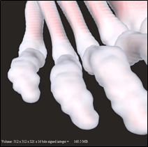
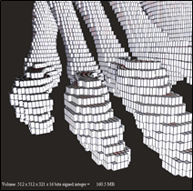
The voxelized rendering mode is also known as “sugar cube” rendering or “Lego-like” rendering. Each voxel is rendered as a box with the dimensions of the voxel. The color of the voxel is determined as usual by the color map (or a custom shader).
Optionally the edges of the voxel box can be drawn in black by setting the voxelOutline field to true (default is false). This mode is very useful for precise editing of the volume voxel-by-voxel.
|
|
|
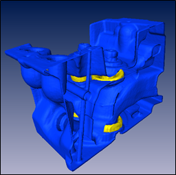
An isosurface is the three-dimensional analog of an isoline. It is a surface that represents points of a constant value within a data volume (also called a level set). SoVolumeIsosurface( C++ | Java | .NET ) is a property node that causes the following SoVolumeRender( C++ | Java | .NET ) node to render one or more isosurfaces instead of volume rendering. Note that using this technique the isosurfaces are only rendered, not geometrically computed. So it is not possible to directly get the geometry corresponding to the rendered isosurface. (The MeshViz extension includes algorithms to extract an isosurface as geometry, see MoMeshIsosurface( C++ | Java ).)
The isovalues to display are specified in the isovalues field. This is an SoMFFloat( C++ | Java | .NET ) field and the number of values in the field determines the number of isosurfaces that will be rendered.
The material properties (e.g. color) of the isosurfaces can be specified using an SoMaterial( C++ | Java | .NET ) node. The multiple value fields diffuseColor and transparency specify the material for each isosurface. The first diffuse color will be for the first isosurface, the second diffuse color for the second isosurface, and so on. All isosurfaces share the first specularColor value and the first shininess value.
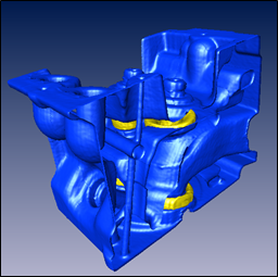
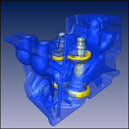
Isosurfaces are lighted with the first directional light found in the scene graph (typically the viewer’s “headlight”). No other lights affect the isosurfaces. It is not necessary to explicitly enable lighting for isosurfaces. Isosurfaces can cast shadows (see image below).
Similar to normal volume rendering, the visual quality of the isosurfaces does depend on the number of samples (slices) specified in the SoVolumeRender( C++ | Java | .NET ) node.
Remember that this is a shader node derived from SoVolumeShader( C++ | Java | .NET ). The effect will usually be undesirable if it is applied to standard geometry (polygons, lines, etc). Therefore applications should generally keep the volume visualization nodes and standard geometry nodes separate in the scene graph (i.e. under different SoSeparator( C++ | Java | .NET ) nodes).
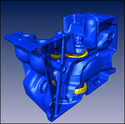
The following example renders two isosurfaces, using the isovalues 30 and 170. The first isosurface will be opaque blue and the second isosurface will be opaque yellow.
C++
// Create nodes
SoVolumeData* pVolData = new SoVolumeData;
pVolData->fileName = "$OIVHOME/src/VolumeViz/Data/engine.vol";

SoMaterial* pMaterial = new SoMaterial;
pMaterial->diffuseColor.set1Value( 0, 0, 0, 1 );
pMaterial->diffuseColor.set1Value( 1, 1, 1, 0 );

SoVolumeRenderIsosurface* pVolIso = new SoVolumeIsosurface;
pVolIso->isovalues.set1Value(0, 30);
pVolIso->isovalues.set1Value(1, 170);

SoVolumeRender *pVolRend = new SoVolumeRender;

// Build scene graph
SoSeparator* pRoot = new SoSeparator;
  SoSeparator* pVolSep = new SoSeparator;
  pVolSep ->addChild( pVolData );
  pVolSep ->addChild( pMaterial );
  pVolSep ->addChild( pVolIso );
  pVolSep ->addChild( pVolRend );
pRoot->addChild( pVolSep );
.NET
// Create nodes
SoVolumeData VolData = new SoVolumeData();
VolData.fileName.Value = "$OIVHOME/src/VolumeViz/Data/engine.vol";

SoMaterial Material = new SoMaterial ();
Material.diffuseColor[0] = new SbColor( 0, 0, 1 );
Material.diffuseColor[1] = new SbColor( 1, 1, 0 );

SoVolumeIsosurface VolIso = new SoVolumeIsosurface();
VolIso.isovalues[0] = 30;
VolIso.isovalues[1] = 170;

SoVolumeRender VolRend = new SoVolumeRender();

// Build scene graph
SoSeparator Root = new SoSeparator();
  SoSeparator VolSep = new SoSeparator();
  VolSep.AddChild( VolData );
  VolSep.AddChild( Material );
  VolSep.AddChild( VolIso );
  VolSep.AddChild( VolRend );
Root.AddChild( VolRend );
Java
// Create nodes
SoVolumeData volData = new SoVolumeData();
volData.fileName.setValue( "$OIVHOME/src/VolumeViz/Data/engine.vol" );

SoMaterial material = new SoMaterial ();
material.diffuseColor.set1Value( 0, 0, 0, 1 );
material.diffuseColor.set1Value( 1, 1, 1, 0 );

SoVolumeIsosurface volIso = new SoVolumeIsosurface ();
volIso.isovalues.set1Value(0, 30);
volIso.isovalues.set1Value(1, 170);

SoVolumeRender volRend = new SoVolumeRender();

// Build scene graph
SoSeparator root = new SoSeparator();
  SoSeparator volSep = new SoSeparator();
  volSep.addChild( volData );
  volSep.addChild( material );
  volSep.addChild( volIso );
  volSep.addChild( volRend );
root.addChild( volRend );
|
|
|
|
|
|
The SoVolumeDataDrawStyle( C++ | Java | .NET ) node specifies the volume rendering style(s) for a volume or for one of the voxel regions of a volume defined by SoVolumeMask( C++ | Java | .NET ) nodes. Styles are specified using the style field. This is a bitmask field and may be set to NONE to disable rendering or any combination of the following values:
VOLUME_RENDER : Volume render the volume mask using its associated transfer function (Default).
ISOSURFACE : Render a set of isosurfaces using the isovalues and isosurfacesMaterial fields.
MASK_BOUNDARY : Render the boundary surface of the mask using the boundaryMaterial field.
Volume rendering always uses the current transfer function and material in the scene graph. Isosurfaces and boundary surfaces use the current material by default, but can optionally be rendered using materials specified in the isosurfacesMaterial and boundaryMaterial fields. Each of these fields can contain a reference to an SoMaterial( C++ | Java | .NET ) node to define the properties of the material. The isovalues field can contain a list of floating point values. An isosurface will be rendered for each value.
![[Important]](../../images/important.jpg) | |
|