SoVolumeShader Class Reference
[Nodes]
 Shader node for volume rendering.
More...
Shader node for volume rendering.
More...
#include <VolumeViz/nodes/SoVolumeShader.h>
Public Types | |
| enum | ShaderPosition { GEOMETRY_MAIN = 0, DATA_COMBINE_FUNCTION, GET_DATA_FUNCTION, FRAGMENT_COMPUTE_COLOR, VERTEX_MAIN, FRAGMENT_MAIN, VERTEX_POSTPROCESSING, CLIPPING_FUNCTION, TESS_VERTEX_SHIFT, CUSTOM_SHADER = 64 } |
Public Member Functions | |
| virtual SoType | getTypeId () const |
| SoVolumeShader () | |
| virtual SoFragmentShader * | setFragmentShader (int pos, const SbString &filenameOrSource, SoShaderObject::SourceType sourceType=SoShaderObject::FILENAME) |
| virtual SoVertexShader * | setVertexShader (int pos, const SbString &filenameOrSource, SoShaderObject::SourceType sourceType=SoShaderObject::FILENAME) |
Static Public Member Functions | |
| static SoType | getClassTypeId () |
| static SbBool | isSupported (SoState *state=NULL) |
Public Attributes | |
| SoSFBool | forVolumeOnly |
| SoSFBool | interpolateOnMove |
Detailed Description
Shader node for volume rendering.
This node manages the VolumeViz GLSL shader pipeline. It is derived from SoShaderProgram and behaves in a similar way. It allows you to supply custom shaders for all VolumeViz rendering shapes (SoVolumeRender, SoOrthoSlice, etc.).
Note: GLSL is the only shading language supported by this node.
SoVolumeShader fields provide different pre-implemented rendering effect options, but the application is free to redefine some stages of the VolumeViz shader pipeline by inserting GLSL shader functions in the shaderObject field (inherited from SoShaderProgram). The shaderObject multi-field contains only application redefined shaders. The position of a shader in the multi-field explicitly specifies the pipeline shader stage to redefine. Customizable stages are described below in the ShaderPosition enum. For example, a seismic application could implement co-blending of multiple volumes by supplying a replacement for the VVizComputeFragmentColor() function in the FRAGMENT_COMPUTE_COLOR position of the shaderObject field.
Note: The advanced rendering options, e.g. lighting, are provided by the SoVolumeRenderingQuality node (a subclass of SoVolumeShader). Generally if an application wants to redefine a stage of the shader pipeline but still be able to use these advanced options, it should create an SoVolumeRenderingQuality node and set the replacement shader functions in the shaderObject field of that node.
VolumeViz provides a shader pipeline API composed of GLSL functions that are automatically loaded. This allows the application to modify existing effects or add new effects with minimum new codes. The VolumeViz GLSL shader pipeline API is described in the VolumeViz Shader API document.
Use the forVolumeOnly field to specify if the shader is to be used for volume rendering or for non-volume rendering (slice, volume geometry, etc). In some cases it may be possible to use the same shader source for both volume and non-volume rendering. However the application must still create two shader nodes, one with the forVolumeOnly field set to TRUE and one with it set to FALSE, even if both nodes load the same shader source file. (This is necessary because the shader source must be compiled with different parameters for the different cases.)
No more than one SoVolumeShader (or derived class) can be used with one volume visualization node, e.g. SoVolumeRender. Since SoVolumeIsosurface and SoVolumeRenderingQuality are derived from this class, only one (or none) of these three nodes can be used at the same time. Exception: Since Open Inventor 7.1 it is possible to use both SoVolumeRenderingQuality and SoVolumeIsosurface with SoVolumeRender.
Remember that this is an SoShaderProgram node. The effect will usually be undesirable if it is applied to non-VolumeViz geometry (polygons, lines, etc). Therefore applications should generally keep the volume visualization nodes and standard geometry nodes separate in the scene graph (i.e. under different SoSeparator nodes).
Reserved texture units:
Because some rendering methods need to create and use special textures, some texture units must be reserved for internal use. The application can specify which texture units VolumeViz should use by setting environment variables (see SoPreferences). The texture units between OIV_FIRST_RESERVED_TEXTURE_UNIT and OIV_FIRST_RESERVED_TEXTURE_UNIT+SoShaderProgramgetNumReservedTextures()-1 inclusive are reserved for internal VolumeViz use. If OIV_FIRST_RESERVED_TEXTURE_UNIT is not set, its default value is SoFragmentShader::getMaxTextureImageUnit() - SoShaderProgram::getNumReservedTextures(). Note: The value returned by SoShaderProgram::getNumReservedTextures() may change between VolumeViz versions. The total number of available texture units depends on the graphics hardware.
Composition with Multiple Data:
When compositing multiple datasets that have different dimensions or extents using a custom shader, it is necessary to convert texture coordinates from one dataset to another in order to fetch the correct data values.
For this purpose, texture coordinates conversion functions are provided in the VolumeViz/vvizStructure.h shader include.
For instance,
vec3 VVizTextureToTextureVec(in VVizDataSetId datasetSrc, in VVizDataSetId datasetDst, in vec3 texCoord);
can be used to convert texture coordinates related to one dataset to texture coordinates related to another dataset.
The conversion is based solely on the transformations applied to each dataset, which are defined by their model matrix and their extent.
Please note that the model matrix of a dataset is defined by to the SoTransformation nodes that are placed before the SoDataSet node in the order of the traversal.
Limitations:
-
Only graphics cards supporting the GLSL language can use this node.
-
Shader filenames beginning with "vviz" are reserved.
Filenames set in a public slot with this prefix will be ignored. - Fragment shaders must not use the GLSL discard keyword when volume rendering is using the ray casting algorithm (the default since v9.0). If discard is used, the rendering will be incorrect. If a fragment should not affect the frame buffer, set it to completely transparent. If you are discarding fragments in the VVizGetData() function (i.e. before assigning color), then you must reserve one entry in the color map to be completely transparent and return the appropriate data value. The easiest way to do this is to make the first color map entry transparent, either explicitly or by setting the SoTransferFunction node's minValue field to 1. Because the VVizGetData() works with normalized data values in the range 0..1, returning 0 will select the transparent entry regardless of the actual data range.
Note: Since the GLSL specification doesn't currently allow the use of any include directive, Open Inventor provides this service through a comment directive. This provides greater flexibility in implementing complex GLSL shaders. Included files are loaded using SoInput and use the same search path order.
//!oiv_include <VolumeViz/vvizCombine_frag.h>
The VolumeViz shader API is described in VolumeViz Shader API.
Available vertex program functions are described in Vertex shaders.
Available fragment program functions are described in Fragment shaders.
Available constants, macros and data structures are described in Data structures and constant.
EXAMPLE
- Load a fragment shader in the COMPUTE_COLOR slot.
- Various important nodes are omitted here for clarity.
- This example could be simplified slightly using the setFragmentShader() convenience method.
- This example could also be simplified slightly using SoFragmentShader's addShaderParameter1i() method.
   // Create an SoVolumeData node
   SoVolumeData* volData = new SoVolumeData();
     volData->dataSetId = 1;
     volSep->addChild( volData );

   // Create an integer uniform parameter for the dataSetId
   SoShaderParameter1i* paramTex1 = new SoShaderParameter1i();
     paramTex1->name = "dataId1";
     paramTex1->value = volData->dataSetId.getValue();

   // Create a fragment shader, load the source file and add the parameter
   SoFragmentShader* fragmentShader = new SoFragmentShader();
     fragmentShader->sourceProgram = SHADER_FILENAME;
     fragmentShader->parameter.set1Value( 0, paramTex1 );

   // Create a shader program and add the fragment shader
   SoVolumeShader* volShader = new SoVolumeShader();
     int shaderPosition = SoVolumeShader::FRAGMENT_COMPUTE_COLOR;
     volShader->shaderObject.set1Value( shaderPosition, fragmentShader );
     volSep->addChild( volShader );
FILE FORMAT/DEFAULT
- SoShaderProgram {
| shaderObject | [ |
| GEOMETRY_MAIN shader | |
| DATA_COMBINE_FUNCTION shader, | |
| GET_DAT_FUNCTION shader, | |
| FRAGMENT_COMPUTE_COLOR shader, | |
| VERTEX_MAIN shader, | |
| VERTEX_MAIN shader, | |
| FRAGMENT_MAIN shader, | |
| ... (reserved) | |
| CUSTOM_SHADER shader | |
| ... (free for apps) | |
| ] | |
| forVolumeOnly | FALSE |
| raycasting | TRUE |
| interpolateOnMove | TRUE |
SEE ALSO
SoShaderProgram, SoVolumeRenderingQuality, SoMultiDataSeparator, SoVolumeIsosurface, SoPreferences
- See related examples:
-
InteractiveThresholding, MarkerPicking, OverlayDisplay, MedicalGPUDataCompose, MedicalIntensityAnisotropy, MedicalMultiChannel, MedicalVolumeTextureCompose, MedicalGammaCorrection, MedicalSimpleShader, HorizonInVolume, HorizonIsolines, HorizonShiftProjection, MultiChannel_ex1, MultiChannel_ex2, AmplitudeVelocity, GpuDataCompose, HorizonGpuCompose, VolumeTextureCompose, SimpleShader, VolumeProjection
Member Enumeration Documentation
Specifies the position of the shader pipeline stages in the field shaderObject.
In other words, use these enumeration values for the first parameter of the set1Value() method when setting a custom shader in the SoVolumeShader node.
- Enumerator:
GEOMETRY_MAIN The main geometry program used for rendering.
Notes: Defining a custom GEOMETRY_MAIN slot is only supported for compatibility. It is not compatible with the volume rendering.
DATA_COMBINE_FUNCTION This shader is used for GPU multi-data composition.
It must contain an application defined data combining function whose prototype is:
VVIZ_DATATYPE VVizCombineData(in vec3 dataCoord);
The subtraction of two volumes can be written in GLSL like this:
   // !oiv_include <VolumeViz/vvizGetData_frag.h>
   // !oiv_include <VolumeViz/vvizCombineData_frag.h>

   uniform VVizDataSetId dataId1;
   uniform VVizDataSetId dataId2;

   VVIZ_DATATYPE VVizCombineData(vec3 tcoord)
   {
     VVIZ_DATATYPE d1 = VVizGetData(dataId1, tcoord);
     VVIZ_DATATYPE d2 = VVizGetData(dataId2, tcoord);
     return d1-d2;
   }
First volume Second volume Subtraction 
NOTE: On the GPU, voxel values are always returned as a normalized value in the range 0..1. If the actual voxel value is needed, the shader function must compute that value using the current data range (see SoDataRange). The application must pass the data range to the shader function as a uniform parameter.
See Fragment shaders for more details.
GET_DATA_FUNCTION This shader is used to access datasets.
It must contain an application defined data accessor function whose prototype is:
VVIZ_DATATYPE VVizGetData(in VVizDataSetId dataset, in vec3 dataCoord);
The default implementation is defined as follows:
 // !oiv_include <VolumeViz/vvizGetData_frag.h>

 // Default 3D DATA interpolation
 VVIZ_DATATYPE VVizGetData(VVizDataSetId tex, vec3 tcoord)
 {
   return VVizGetRawData(tex, tcoord);
 }
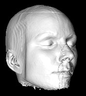
This function can be used to apply filters on each data volume. The following example shows how to make a smoothing filter which will remove some noise:
 // !oiv_include <VolumeViz/vvizGetData_frag.h>
 VVIZ_DATATYPE VVizGetData(in VVizDataSetId dataset, vec3 tcoord)
 {
   vec3 voxelDim = VVizGetVoxelDimensions(dataset);
   vec3 du = vec3(voxelDim[0], 0., 0.);
   vec3 dv = vec3(0., voxelDim[1], 0.);
   vec3 dw = vec3(0., 0., voxelDim[2]);

  return 1./6.*(VVizGetRawData(dataset, tcoord-du).w+VVizGetRawData(dataset, tcoord+du).w+
                VVizGetRawData(dataset, tcoord-dv).w+VVizGetRawData(dataset, tcoord+dv).w+
                VVizGetRawData(dataset, tcoord-dw).w+VVizGetRawData(dataset, tcoord+dw).w);

 }
Non filtered data Filtered data 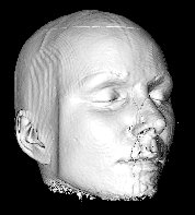
NOTE: On the GPU, voxel values are always returned as a normalized value in the range 0..1. If the actual voxel value is needed, the shader function must compute that value using the current data range (see SoDataRange). The application must pass the data range to the shader function as a uniform parameter.
See Fragment shaders for more details.
FRAGMENT_COMPUTE_COLOR This shader is used to compute the current fragment color.
Note: VVizComputePreIntegrated should only be called when SoVolumeRendering::renderMode is set to VOLUME_RENDERING (the default). It is not appropriate for MIN, MAX, etc composition.
It must contain an application defined compute fragment color function whose prototype is:
 // For an SoVolumeRender node
 vec4 VVizComputeFragmentColor(in VVizDataSetId dataset, in vec3 rayDir, inout VVizVoxelInfo voxelInfoFront, in VVizVoxelInfo voxelInfoBack, in int mask);
 // For all other VolumeViz shape nodes (SoOrthoSlice, SoObliqueSlice, SoVolumeSkin ...)
 vec4 VVizComputeFragmentColor(in VVIZ_DATATYPE vox, in vec3 dataCoord);
This function can be used to do co-blending on multiple data volumes. The following example shows how to blend two volumes:
   // !oiv_include <VolumeViz/vvizGetData_frag.h>
   // !oiv_include <VolumeViz/vvizTransferFunction_frag.h>

   uniform VVizDataSetId data1;
   uniform VVizDataSetId data2;

   vec4 blend(in vec3 texCoord)
   {
     VVIZ_DATATYPE index1 = VVizGetData(data1, texCoord);
     vec4 data1Color = VVizTransferFunction(index1, 0);

     VVIZ_DATATYPE index2 = VVizGetData(data2, texCoord);
     vec4 data2Color = VVizTransferFunction(index2, 1);

     // Color modulated by intensity from volume2
     data2Color.rgb *= data1Color.r;
     data2Color.a   *= data1Color.a;
     return res;
   }

   // Implement VVizComputeFragmentColor for slice nodes
   vec4 VVizComputeFragmentColor(in VVIZ_DATATYPE vox, in vec3 texCoord)
   {
    return blend(texCoord);
   }

   // Implement VVizComputeFragmentColor for SoVolumeRender
   vec4 VVizComputeFragmentColor(in VVizDataSetId data, in vec3 rayDir, inout VVizVoxelInfo voxelInfoFront, in VVizVoxelInfo voxelInfoBack, in int maskId)
   {
     return blend(voxelInfoFront.texCoord);
   }
Composition of multiple independent volumes:
The following code gives an example of how to blend two independent volumes (different dimensions or extents).
The main difference with the previous example is that this one must transform the texture coordinates passed as parameter to the correct space before calling VVizGetData().// !oiv_include <VolumeViz/vvizStructure.h> // !oiv_include <VolumeViz/vvizGetData_frag.h> // !oiv_include <VolumeViz/vvizTransferFunction_frag.h> uniform VVizDataSetId DataSet1; uniform VVizDataSetId DataSet2; vec4 alphaBlend(in vec4 dst, in vec4 src) { vec4 res = src.a * (1.0 - dst.a) * vec4(src.rgb, 1.0) + dst.a * vec4(dst.rgb, 1.0); res.rgb = (res.a != 0.0) ? (res.rgb / res.a) : vec3(0.0); return res; } vec4 blend(in VVizDataSetId data, in vec3 texCoord) { vec4 outputColor = vec4(0.0); vec3 data1Coord = VVizTextureToTextureVec(data, DataSet1, texCoord); if (!VVizIsOutsideTexture(data1Coord)) { VVIZ_DATATYPE index1 = VVizGetData(DataSet1, data1Coord); vec4 data1Color = VVizTransferFunction(index1, DataSet1); outputColor = alphaBlend(outputColor, data1Color); } vec3 data2Coord = VVizTextureToTextureVec(data, DataSet2, texCoord); if (!VVizIsOutsideTexture(data2Coord)) { VVIZ_DATATYPE index2 = VVizGetData(DataSet2, data1Coord); vec4 data2Color = VVizTransferFunction(index2, DataSet2); outputColor = alphaBlend(outputColor, data2Color); } return outputColor; } // Implement VVizComputeFragmentColor for slice nodes vec4 VVizComputeFragmentColor(in VVIZ_DATATYPE vox, in vec3 texCoord) { return blend(VVizGetDefaultDataSet(), texCoord); } // Implement VVizComputeFragmentColor for SoVolumeRender vec4 VVizComputeFragmentColor(in VVizDataSetId data, in vec3 rayDir, inout VVizVoxelInfo voxelInfoFront, in VVizVoxelInfo voxelInfoBack, in int maskId) { return blend(data, voxelInfoFront.texCoord); }
See Fragment shaders for more details.
NOTE: enumeration value available since Open Inventor 9.0
VERTEX_MAIN Main vertex shader used for rendering.
This stage should not be redefined unless you know exactly what you are doing. If the goal of your application is to compute specific varying attributes to pass to the fragment shader you should use the shaderPosition slot named VERTEX_POSTPROCESSING.
Notes: Defining a custom VERTEX_MAIN slot is only supported for compatibility. It is not compatible with the raycasting volume rendering technique which is now the default for SoVolumeRender.
See Vertex shaders for more details.
FRAGMENT_MAIN Main fragment shader used for rendering.
This stage should not be redefined unless you know exactly what you are doing. If the goal of your application is to blend colors or add effects to the existing pipeline you should use the shaderPosition slot named FRAGMENT_COMPUTE_COLOR.
Notes: Defining a custom FRAGMENT_MAIN slot is only supported for compatibility. It is not compatible with the raycasting volume rendering technique.
See Fragment shaders for more details.
VERTEX_POSTPROCESSING Method called at the end of the VolumeViz vertex shader stage.
This shader allows the application to generate custom varying values at the vertex shader stage for use in the fragment shader stage.See Vertex shaders for more details.
NOTE: enumeration value available since Open Inventor 9.0CLIPPING_FUNCTION This method can be used to implement a custom clipping algorithm.
Note that when using this method, it may not always be possible for VolumeViz to correctly manage slicing artifacts. You have to use SoVolumeRender::samplingAlignement = BOUNDARY_ALIGNED to avoid slicing artifacts.
When applying a custom clipping function with SoVolumeRenderingQuality::voxelizedRendering = TRUE, the voxels will be hollow.
NOTE: enumeration value available since Open Inventor 9.7TESS_VERTEX_SHIFT Shader function used to modify the position of vertices during HeightField rendering.
This shader slot must be set with an SoTessellationEvaluationShader.
The shader must contain a function whose prototype is:
vec3 VVizTessVertexShift( in vec3 position, in vec2 texCoord );
The input position represents the 3D position of a vertex on the HeightField surface in model space: X and Y coordinates are mapped to [-1, 1] and the Z coordinate corresponds to the data set value, either normalized to [0, 1] for unsigned integer data types, [-1, 1] for signed integer datatypes, or used "as is" for floating point data types.
texCoord represents the 2D texture coordinate associated with the position.
The position returned by the function is expected to be the modified vertex position and must also be set in model space.
A vertex shift using a shift texture can be written in GLSL like this:
 // !oiv_include <VolumeViz/vvizVertexShift_tess.h>

 uniform sampler2D shiftTexture;

 vec3
 VVizTessVertexShift( in vec3 position, in vec2 texCoord )
 {
   return position + texture( shiftTexture, texCoord ).xyz;
 }
Notes & Limitations:
- This shader is available only for HeightField rendering. It is ignored during volume rendering and slice rendering.
- The default shader returns the input position unmodified.
- Although the shader must be an SoTessellationEvaluationShader, the GLSL function VVizTessVertexShift() will also be called internally during the tessellation control stage and the fragment stage, so the shader must only use the GLSL API that is common to those 3 stages.
- Bounding Box, Tile Loading & Picking: Because this shader slot allows to modify the geometry of the rendered object, a discrepancy may arise that can lead to a misaligned bounding box, defective tile loading and incorrect picking values. These issues can be avoided by deriving the SoHeightFieldGeometry class and overriding the methods voxelToXYZ() and XYZToVoxel(). The voxelToXYZ() method is used by the bounding box computation and the tile loading and would need to re-implement the vertex shift transformation. The XYZToVoxel(SbVec3f) method is used for picking and would need to implement the inverse vertex shift transformation in order to be correct.
CUSTOM_SHADER This position and all subsequent positions CUSTOM_SHADER+x are freely available for user-defined shaders.
NOTE: enumeration value available since Open Inventor 9.0
Constructor & Destructor Documentation
| SoVolumeShader::SoVolumeShader | ( | ) |
Constructor.
Member Function Documentation
| static SoType SoVolumeShader::getClassTypeId | ( | ) | [static] |
Returns the type identifier for this class.
Reimplemented from SoShaderProgram.
Reimplemented in SoVolumeIsosurface, and SoVolumeRenderingQuality.
| virtual SoType SoVolumeShader::getTypeId | ( | ) | const [virtual] |
Returns the type identifier for this specific instance.
Reimplemented from SoShaderProgram.
Reimplemented in SoVolumeIsosurface, and SoVolumeRenderingQuality.
Returns TRUE if SoVolumeShader is supported by the current graphics board.
When using a debug build of Open Inventor, some "no context available" warning messages may be generated. You can ignore them or see SoGLExtension for an example of using SoGLContext to avoid them.
| virtual SoFragmentShader* SoVolumeShader::setFragmentShader | ( | int | pos, | |
| const SbString & | filenameOrSource, | |||
| SoShaderObject::SourceType | sourceType = SoShaderObject::FILENAME | |||
| ) | [virtual] |
Creates a fragment shader with the given filename and add it at the given pos.
Return value is the new fragment shader.
Reimplemented from SoShaderProgram.
| virtual SoVertexShader* SoVolumeShader::setVertexShader | ( | int | pos, | |
| const SbString & | filenameOrSource, | |||
| SoShaderObject::SourceType | sourceType = SoShaderObject::FILENAME | |||
| ) | [virtual] |
Creates a vertex shader with the given filename and adds it at the given pos.
- Returns:
- the new vertex shader.
Reimplemented from SoShaderProgram.
Member Data Documentation
Set to TRUE if the shader should be called for volume rendering (SoVolumeRender).
Set to FALSE if it should be called for other VolumeViz shapes (SoOrthoSlice, SoObliqueSlice, SoVolumeSkin, volume geometry, etc). Default is FALSE.
TRUE means that if the shader uses texture coordinates, they will be 3D texture coordinates. FALSE means they will be 2D texture coordinates.
In some cases it may be possible to use the same shader source for both volume and non-volume rendering. However the application must still create two shader nodes, one with TRUE and one with FALSE, even if both nodes load the same shader source file. (This is necessary because the shader source must be compiled with different parameters for different cases.)
When set to FALSE, interpolation between LDM tiles (across the tile boundary) is not done when rendering in interactive mode.
This increases the interactive rendering frame rate at the cost of some rendering artifacts at the tile boundaries (seen as horizontal and vertical "lines" in the rendered image) and a small lag when switching between still and interactive. If your rendering shaders do not need to access voxel's neighbor (for lighting or gradient computation for instance), you should set this field to TRUE as the cost of interpolation is not significant in this case.
Default is TRUE.
NOTE: field available since Open Inventor 9.0The documentation for this class was generated from the following file:
- VolumeViz/nodes/SoVolumeShader.h