Engines are generally used in two different ways:
To animate parts of a scene
To constrain one part of a scene in relation to some other part of the scene
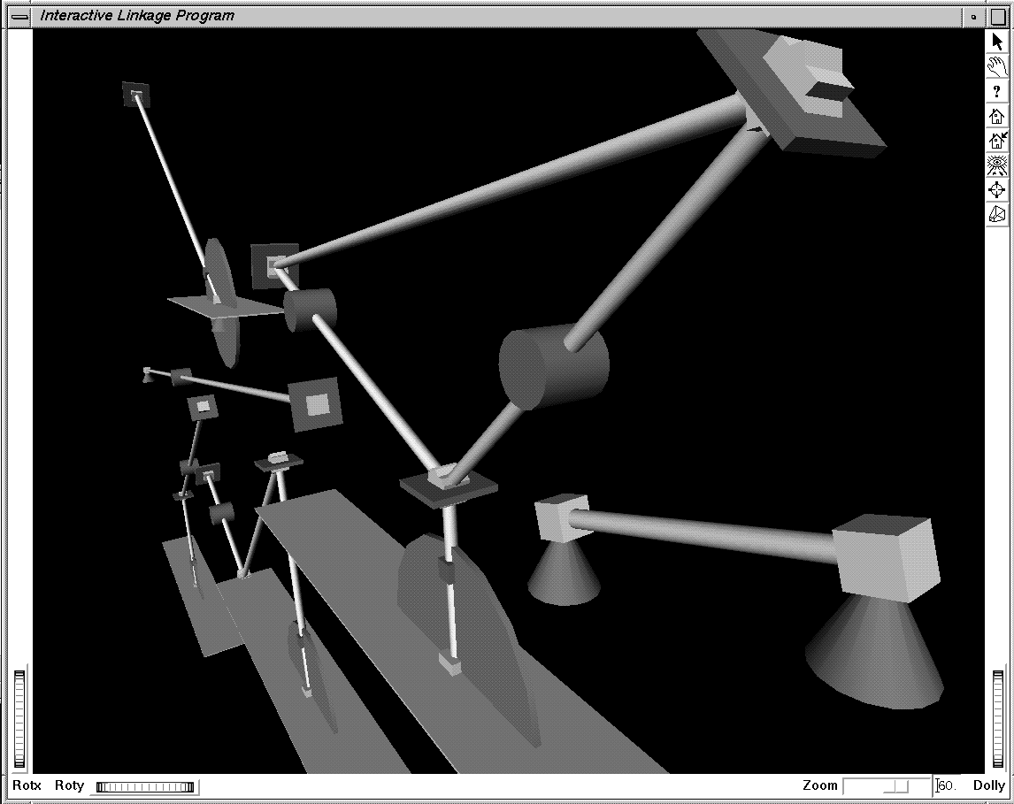
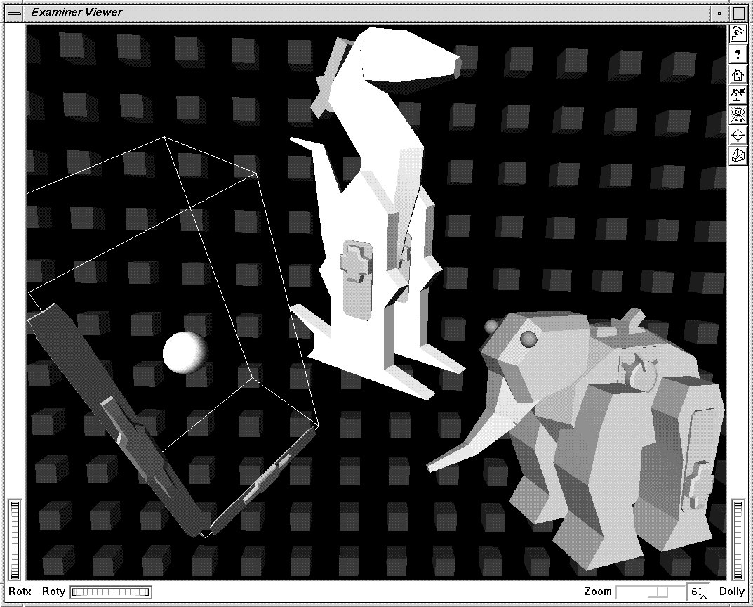
Figure 15.1, “ Mechanisms Made from a Set of Link Classes ” and Figure 15.2, “ Objects That Use Engines for Animation and Placement ” show applications that use engines. In Figure 15.1, “ Mechanisms Made from a Set of Link Classes ”, four different classes of links are created—struts, hinges, cranks, and double struts. Engines are used to connect links end-to-end. The objects in Figure 15.2, “ Objects That Use Engines for Animation and Placement ” use engines to edit transform nodes that animate the animals and objects in the scene.
As shown in Example 15.1, “ Using the Real-Time Global Field ” later in this chapter, you can connect parts of a scene to a clock so that animation in the scene occurs in relation to changes in time. Example 15.6, “ Using a Calculator Engine ” shows an example of constraints, where the movement of an object is constrained to a set path.
You can think of an engine as a black box that receives input values, performs some operation on them, and then copies the results into one or more outputs. Both the inputs and the outputs of the engine can be connected to other fields or engines in the scene graph. When an engine's output values change, those new values are sent to any fields or engines connected to them.
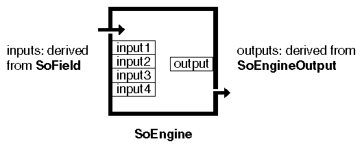
An engine, shown in Figure 15.3, “ Anatomy of an Engine ”, has inputs derived from SoField SoField SoField and outputs derived from SoEngineOutput SoEngineOutput SoEngineOutput . Each engine evaluates a built-in function when its input values change. The resulting output values are then sent to all fields and engines connected to that engine. Because SoEngine SoEngine SoEngine is derived from the SoBase SoBase SoBase class, it includes methods for reading and writing to files.
For example, the engine shown in Figure 15.3, “ Anatomy of an Engine ” could represent SoComposeVec4f SoComposeVec4f SoComposeVec4f , an engine that creates an SoMFVec4f SoMFVec4f SoMFVec4f object. It has four inputs of type SoMFFloat SoMFFloat SoMFFloat and one output of typeSoMFVec4f SoMFVec4f SoMFVec4f . This engine composes the four inputs into one SoMFVec4f SoMFVec4f SoMFVec4f output.


