SoUniformGridClipping Class Reference
[Nodes]
 Clips a volume using a 2D surface.
More...
Clips a volume using a 2D surface.
More...
#include <VolumeViz/nodes/SoUniformGridClipping.h>
Public Types | |
| enum | Axis { X, Y, Z } |
Public Member Functions | |
| virtual SoType | getTypeId () const |
| SoUniformGridClipping () | |
Static Public Member Functions | |
| static SoType | getClassTypeId () |
| static SbBool | isSupported (SoState *state=NULL) |
| static int | getMaxNumberOfUniformGrids (SoState *state=NULL) |
Public Attributes | |
| SoSFBox3f | extent |
| SoSFEnum | axis |
| SoSFFloat | thickness |
| SoSFBool | clipBelow |
| SoSFBool | clipAbove |
| SoSFFloat | undefinedValue |
Deprecated | |
|
| |
| SoDEPRECATED SoSFBox3f | size |
Detailed Description
Clips a volume using a 2D surface.
The SoUniformGridClipping node specifies a clipping surface defined by a clipping axis (axis field),a bounding box (extent field) in world coordinates and a uniform scalar clipping grid (a 2D array of height values). This tool provides an efficient way for seismic applications to clip volume rendering against horizon surfaces (see also SoUniformGridProjectionClipping). A flat clipping surface with non-zero thickness can also be used in medical applications to implement "thick slice" rendering. The clipping grid does not need to have the same dimensions as the volume to be clipped (it will be sampled and interpolated). The clipping grid may be rotated and translated by standard Open Inventor transform nodes.
The height values are specified using a 2D texture. Each texel is a normalized value that, together with the extent, specifies a height. For integer valued textures, the range of the integer type (e.g. 0..255 for byte values) is normalized to the floating point range 0..1. For float valued textures the values should already be in the range 0..1. Each normalized value specifies a height based on the range of values in the extent box along the specified clipping axis. The default clipping axis is the Y axis.
NOTE: For integer valued textures this is similar to the way values are interpreted for the SoHeightFieldGeometry node. However for float valued textures it is quite different because the SoHeightFieldGeometry node interprets float values as actual height values and ignores the extent values.
It is also possible to specify an "undefined" value using the undefinedValue field. Texels with this value will clip all voxels above and below the surface. The default undefined value is Nan (Not a Number).
The X, Y and Z coordinates of the extent are in the same coordinate system as the volume extent. They specify the bounding box of the clipping surface and also the range of height values that can be specified with the normalized values in the height field texture. They are typically, but not necessariliy, set to the same values as the volume extent. The extent of the clipping surface may be larger than the volume extent. In this case the volume is only clipped where its extent overlaps with the surface. The extent of the clipping surface may also be smaller than the volume extent. In this case the volume is clipped to the "horizontal" extent of the clipping surface (the dimensions perpendicular to the clipping axis). However along the clipping axis the volume is only limited by the surface itself, not by its extent.
SoUniformGridClipping is derived from SoTexture2 , so the clipping grid texture can be specified by setting the filename field or by directly setting the image field. Directly setting the image field is convenient if the height field data is floating point. All the usual texturing parameters apply. Wrapping and filtering modes are particularly important. Setting wrap mode to something other than CLAMP_TO_EDGE may cause unwanted interpolation on edges. Setting filter mode to NEAREST will give a blocky result which may or may not be desired.
The format of the texture used for the grid should be the LUMINANCE* type for best performance. For example, a grayscale .png file will automatically be in this format. We suggest to use LUMINANCE_FLOAT32 explicitely for floating point data in order to preserve floating point precision. If no red component is available in the format used (for example ALPHA texture...), the grid will be totally flat.
Each clipping surface texture must be stored in a different OpenGL texture unit. One that is not currently used by VolumeViz for multi-data composition (i.e., a texture unit number greater than the highest dataSetId plus 1). Setting the texture unit for a clipping surface is done using the SoTextureUnit node, just like with any texture node.
The SoUniformGridProjectionClipping node provides an alternate way to specify the clipping grid. This node may be more convenient when clipping using surface geometry that is already in the scene graph, for example an SoHeightFieldRender node.
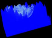
The figure below shows the result (right) of applying the left texture to a volume.
-
Clipping surface Clipping applied to a volume 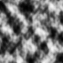
The following code shows one way to achieve this result. It loads the clipping surface "horizon2D.png" and puts it in texture unit 2:
   SoTextureUnit *texUnit2 = new SoTextureUnit();
     texUnit2->unit = 2;
   SoUniformGridClipping *grid = new SoUniformGridClipping();
     grid->filename = "horizon2D.png";

   SoSeparator* volSep = new SoSeparator();
     volSep->addChild( volumeData );
     volSep->addChild( transferFunction );
     volSep->addChild( texUnit2 );
     volSep->addChild( grid );
     volSep->addChild( volumeRender );
   root->addChild( volSep );
The uniform grid clipping node provides both clipAbove and clipBelow boolean fields. By default only clipAbove is true. Using a pair of grid clipping nodes, one with clipAbove and one with clipBelow, allows clipping between two surfaces. This is useful in seismic applications to clip between two "horizon" surfaces. Note that if both of these fields are true and the thickness field is zero then the entire volume will be clipped.
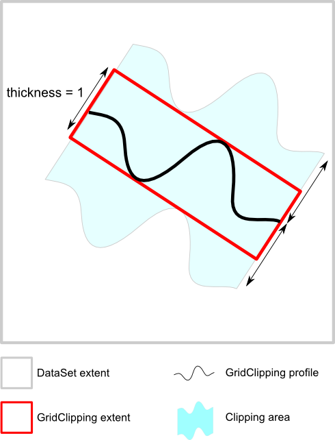
The thickness field expands the clipping surface in both directions perpendicular to the surface.The value of this field is specified in 0..1 normalized units spanning the specified extent of the surface. A completely flat clipping surface with thickness greater than zero can be used to implement "thick slice" (aka "thin slab") rendering. A transform node, for example SoTransform , can be used to position and orient the clipping surface. In this case the transform node and the clipping surface node should usually be placed under an SoTransformSeparator node. This allows the surface to clip the volume primitives, but prevents the transform node from affecting the volume primitives. Remember that, as usual, the transform node will rotate the clipping surface around the origin (0,0,0) of the world coordinate system.
-
Clipping surface thicknes 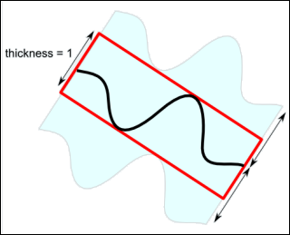

Notes:
- When using a custom SoVolumeShader with this node and redefining the main() function, you must call VVizClipVoxel() in the main() function if you are writing a fragment shader or VVizCalcDistToUniformGrid() if it's a vertex shader. If you don't do this, you will get a GLSL compilation error or clipping won't work.
Limitations:
-
Only graphics cards supporting the GLSL language can use this node.
- The maximum number of SoUniformGridClipping nodes that can be applied to the same volume is limited to getMaxNumberOfUniformGrids(). This limitation depends on the maximum number of sets of OpenGL texture coordinates supported on the graphics board (GL_MAX_TEXTURE_COORDS), which is typically 8, minus 3 sets used elsewhere in VolumeViz, leaving 5 for uniform grids.
FILE FORMAT/DEFAULT
- UniformGridClipping {
| axis | Y |
| extent | -1,0,-1 1,1,1 |
| filename | "" |
| image | 0 0 0 |
| wrapS | CLAMP_TO_EDGE |
| wrapT | CLAMP_TO_EDGE |
| model | MODULATE |
| enableCompressedTexture | FALSE |
| blendColor | 0 0 0 |
| enableBorder | FALSE |
| borderColor | 0 0 0 0 |
| maxAnisotropy | 1.0 |
| minFilter | AUTO |
| magFilter | AUTO |
| loadingMode | AUTO |
| useAutoMipmap | FALSE |
| internalFormat | AUTO_INTERNAL_FORMAT |
| thickness | 0 |
| clipBelow | FALSE |
| clipAbove | TRUE |
SEE ALSO
SoVolumeRender, SoPreferences, SoShaderProgram, SoTexture2, SoTextureUnit, SoVolumeClippingGroup, SoVolumeIsosurface, SoVolumeRenderingQuality, SoUniformGridProjectionClipping
- See related examples:
Member Enumeration Documentation
Constructor & Destructor Documentation
| SoUniformGridClipping::SoUniformGridClipping | ( | ) |
Constructor.
Member Function Documentation
| static SoType SoUniformGridClipping::getClassTypeId | ( | ) | [static] |
Returns the type identifier for this class.
Reimplemented from SoTexture2.
Reimplemented in SoUniformGridProjectionClipping.
| static int SoUniformGridClipping::getMaxNumberOfUniformGrids | ( | SoState * | state = NULL |
) | [static] |
Returns the maximum number of clipping surfaces supported by the hardware.
| virtual SoType SoUniformGridClipping::getTypeId | ( | ) | const [virtual] |
Returns the type identifier for this specific instance.
Reimplemented from SoTexture2.
Reimplemented in SoUniformGridProjectionClipping.
Returns TRUE if uniform grid clipping is supported by the graphics board.
The GPU must support GLSL. Check the maximum number of clipping surfaces using getMaxNumberofUniformGrids.
When using a debug build of Open Inventor, some "no context available" warning messages may be generated. You can ignore them or see SoGLExtension for an example of using SoGLContext to avoid them.
Member Data Documentation
Height axis: X, Y, or Z.
Use enum Axis . Default is Y.
NOTE: field available since Open Inventor 8.0Bounding box of the surface in 3D geometric coordinates.
Default is a box of size (2, 1, 2) with its back left corner at (-1, 0, -1).
NOTE: field available since Open Inventor 8.0
| SoDEPRECATED SoSFBox3f SoUniformGridClipping::size |
- Deprecated:
-
Deprecated since Open Inventor 8000
Use SoUniformGridClipping::extent instead.
Defines a clipping thickness in the axis direction.
Ignored if set to 0. Default is 0;
Value is in the normalized extent space (can be seen as a percentage of the extent).
Notes:
- If thickness is 0 and clipBelow and clipAbove are both TRUE then the whole volume is clipped.
- A value greater than 1.0 makes sense only if the extent of the SoUniformGridClipping is smaller than the extent of the volume data it applies to.
Texels in the clipping texture with this value will clip all voxels above and below the surface.
Default is NaN (not a number).
The documentation for this class was generated from the following file:
- VolumeViz/nodes/SoUniformGridClipping.h