The following document contains the release notes for Open Inventor 10.11 (March 2022)
See below the list of enhancements and new features included in this version.
- In the previous versions of OpenInventor, thanks to the class SoMultiDataSeparator, multiple volume datasets can be combined or blended together. However, it is not possible if the datasets have not the same extent, position, dimension and tile size. This limitation has been removed for most types of renderings volume, slice and skin.
- The default volume rendering (SoVolumeRender) performs an alpha blending on all the volume datasets contained in an SoMultiDataSeparator. The rendering area is the union of these volume extents.
- The slices and the skin depend on a single dataset because this type of rendering is associated with properties of a volume (e.g., slice number and position in each dimension). This volume data can be specified using the new field named dataSetId available for SoOrthoSlice, SoObliqueSlice, SoFenceSlice, SoVolumeSkin and SoROI.
- However, the rendering behavior can be customized using a SoVolumeShader. All the data contained in a SoMultiDataSeparator are available through the Shader API. Thus, custom volume combinations can be implemented for volume, slice or skin renderings.
- New shader functions are available for the SoVolumeShader slots, for instance, to transform texture coordinates from a volume to another. The new API is available here.
- An existing example has been updated to show one possible way of blending two volume datasets and can be found in these folders:
- C++: $OIVHOME/examples/source/VolumeViz/multiData/AmplitudeVelocity
- .NET: $OIVNETHOME/examples/source/VolumeViz/AmplitudeVelocity
- Java: $OIVJHOME/examples/volumeviz/sample/amplitudeVelocity
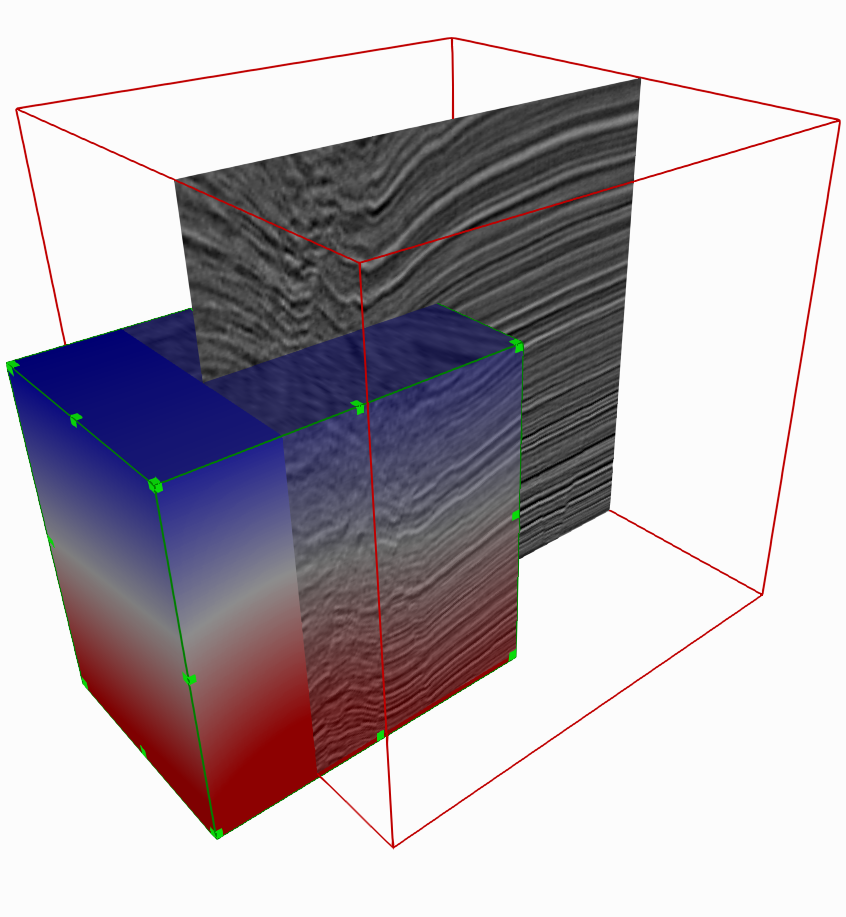
- The following image comes from this example
- The Skin of a first volume (velocity) combined with a second volume (amplitude) in the overlapping region
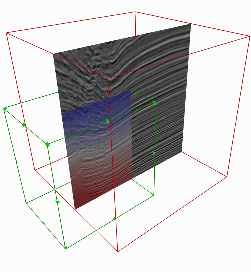
- The next image shows an orthogonal slice (SoOrthoSlice) attached to the second volume (amplitude) combined with the first volume (velocity) in the overlapping region
- Already available in the rendering of height fields (see SoHeightFieldGeometry), the concept of undefined voxels and value has been added for volume data. Basically, an undefined voxel is not rendered and does not impact the rendering of its neighbors. Interpolation never occurs between a defined voxel and an undefined voxel.
- A voxel is considered undefined when its value equals the new field undefinedValue added in the class SoDataSet.
- The classes SoVolumeRender, SoOrthoSlice, SoObliqueSlice, SoFenceSlice and SoVolumeSkin take into account this new field and do not render any undefined voxels.
- Limitations :
- The feature is not yet supported under CPU rendering
- Handling undefined voxels can slow down the rendering of VolumeViz. This feature is particularly sensitive to the size of the rendering area containing the displayed volume
- Combining multiple volumes can lead to undefined rendering results if the volumes do not have the same undefined value
- A new example is available to show the benefit of undefined voxels on the rendering at the boundary of a defined region. It can be found in following folders:
- C++ : $OIVHOME/examples/source/VolumeViz/UndefinedVoxels
- .NET : $OIVNETHOME/examples/source/VolumeViz/UndefinedVoxels
- Java : $OIVJHOME/examples/volumeviz/sample/undefinedVoxels
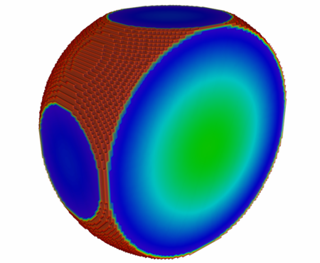
- The illustrations below show the benefit of the feature. The scene contains a simple arbitrary volume clipped by an SoOrthoSlice (not visible).
- In the first one, undefined voxels feature is disabled, meaning all voxels are taken in account for interpolation. This result in an unpleasant red artifact at the boundaries of the volume.
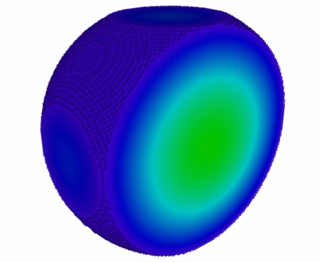
- In the second one, where Undefined Voxels is enabled, the result is obviously better.
- Open Inventor 10.11 supports sparse data, i.e., a tile can be empty and no data is stored neither in CPU memory nor in GPU memory. The rendering of regular tiles (i.e., not empty) is not impacted by an adjacent empty tile. No voxel interpolation occurs at the frontier between a normal tile and an empty tile. A tile is considered empty when the method readTile in SoVolumeReader returns a null pointer, or an empty buffer.
- In order to ease the use of an SoOrthoSliceDragger in your application , the extent and dimension are now automatically retrieved from the SoVolumeData on the state. Thus, it is no longer necessary to manually set the fields volumeDimension and volumeExtent which are now deprecated.
- This type of configuration relies on the Mesa library which uses only CPU capability. Even if the rendering is slower than using a GPU, this is a new option particularly interesting to reduce server costs. Additional details and limitations are described in the new chapter CPU rendering with Mesa 3D of the user's guide.
- Open Inventor 10.11 processes correctly the rendering order of a custom OpenGL node derived from SoShape that needs alpha blending (i.e. non opaque object). This facilitates the migration of source code from Open Inventor 9 to Open Inventor 10, as the custom OpenGL code can be kept as is.
- When you have a structured mesh without edges rendering (when MoDrawStyle::displayEdges is false), the first rendering time is at least two times shorter. The most noticeable improvement occurs, for example, when displaying a MoMeshSkin or a thick MoMeshSlab with a cell filter from a large structured 3D mesh.
- The time to pick and get detail information on an extracted surface has been significantly reduced on a surface containing millions of quadrangles or triangles extracted from a structured mesh. Such improvement is the consequence of new algorithm implemented on the GPU.
- Rendering a shape extracted from a very large mesh can be quite long in particular when both the polygon faces and their outline edges must be displayed (when MoDrawStyle::displayEdges and MoDrawStyle::displayFaces(C++|Java) are true).
- As of Open Inventor 10.11 the rendering can be automatically done in 2 passes in order to speed-up the initial rendering. The first pass displays the surface without the outline edges while the second one displays them later. The duration between the two passes depends on the number of extracted triangles or quadrangles : it can varies from few tenths of a second up to few seconds. The application is not sticky between the two passes, so that the end user can move the camera for instance. The rendering in two passes occurs only when there is a noticeable benefit to the end user, ie when the surface contains millions of polygons (see BeyondCell example).
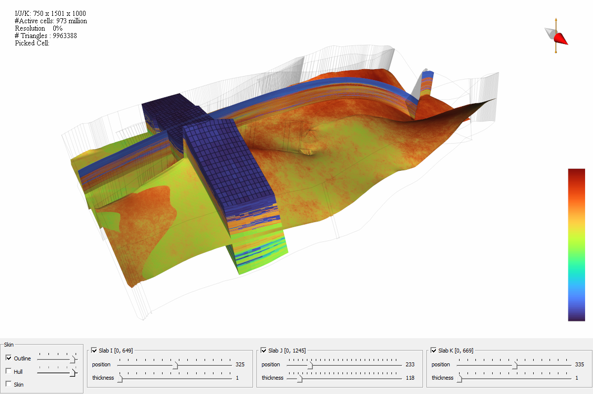
- A new example BeyondCell is provided in C++. It allows to visualize efficiently very large O&G reservoir grids and it introduces the concept of multiple resolutions hierarchy of the grid geometry and properties. The use of multi-resolution highlights the benefit for the end user experience.
- This example is an important step to a project that has been initially described in February 2021 here
- The example is provided in the folder $OIVHOME/examples/source/MeshVizXLM/demonstrators/BeyondCell and all details can be found here.
- Even if a small grid reservoir dataset is provided in $OIVHOME/examples/data/MeshVizXLM/Reservoir/MultiresGrids, some larger grids are also provided and can be downloaded here. To evaluate the benefit of the multi-resolution using BeyondCell, we strongly suggest loading the larger grids. Instructions to load larger grids instead of the small embedded one are available here.
- The following image coming from BeyondCell shows a grid of 973M cells where the vertical thick slab uses a low resolution of this grid while the two others use the full resolution.
- Each sub resolution data of these reservoir grids have been generated from the initial dataset using an automatic converter tool. It uses some advanced compression technics and detects automatically the main characteristics of the geometry of the grid such as faults, undefined regions (dead cells) or pinched cells. Those characteristics are preserved in the output resolutions in order to have the highest possible rendering quality on each sub resolutions.
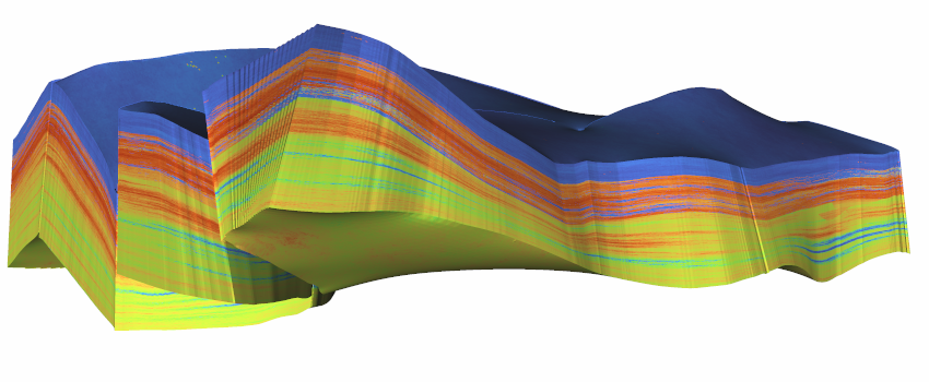
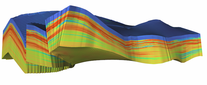
- The gallery below shows that despite the loss of resolution, the geometrical structure and properties of the reservoir are well kept. Here we go from full resolution to 1/8, 1/64 and finally 1/512 and still offer a very good level of interpretation.
- The paddingValue field has been added to the SoSurfaceUnfoldingProcessing3d engine. This parameter defines the value for output voxels having no correspondence in the input image. Its default value is 0, which is equivalent to the previous behavior.