Materials and normals are bound to shape nodes in different ways. The first part of this discussion focuses on material binding, which is how the current materials specified in an SoMaterial( C++ | Java | .NET ) node are mapped onto the geometry of the shape nodes that use that particular material. Since normal binding is analogous to material binding, this initial discussion focuses on material binding. (See Example 5.1, “ Creating a Face Set ” earlier in this chapter for an example of using a normal binding node.)
An SoMaterialBinding( C++ | Java | .NET ) node contains a value that describes how to bind materials to shapes. These values include the following:
Each shape node interprets the binding type somewhat differently. For example, an SoSphere( C++ | Java | .NET ) node does not have parts, faces, or indices, so those binding types (PER_PART, PER_FACE, PER_VERTEX) are meaningless for spheres. You can regard the value specified in the material-binding node as a hint to the shape about binding. If you specify a value that makes no sense for a particular shape, such as PER_FACE for a cylinder, the shape interprets the information the best it can (in this case, it uses OVERALL, since a cylinder has no faces). See the Open Inventor C++ Reference Manual for information on how each shape interprets the different binding types.
Suppose you specify PER_PART for a cylinder. The cylinder has three parts (sides, top, bottom). If the current material contains three values—for example, orange, purple, yellow—those values are used for the three parts of the cylinder, producing orange sides, a purple top, and a yellow bottom. But what happens if the number of current materials is greater than the number of parts? As you might guess, Inventor simply ignores the extra materials if they're not required. (If the current material list contains five values, your cylinder ignores the last two values.)
If the current material contains fewer values than the binding requires, Inventor cycles through the current values as often as needed. For example, if you specify PER_FACE for a cube and the current materials list contains three values (violet, periwinkle, teal), the results are as follows:
So far, you've been using the values in the current material in order. You can, however, also use the current material values in a new order if you specify either PER_FACE_INDEXED or PER_VERTEX_INDEXED for an indexed vertex shape or PER_PART_INDEXED for a shape that has parts. When you use these types of binding, Inventor refers to the materials-index field of the shape node (for example, SoIndexedFaceSet( C++ | Java | .NET ), SoIndexedLineSet( C++ | Java | .NET )). Instead of starting with the first material and working through the list, Inventor indexes into the materials list in whatever order you specify.
As an example, consider a tetrahedron, represented as an SoIndexedFaceSet( C++ | Java | .NET ). The current materials list (in an SoMaterial( C++ | Java | .NET ) node) contains the following values:
Material List
and the materialIndex field (in an SoIndexedFaceSet( C++ | Java | .NET ) node) contains these values:
Material Index
1
1
0
2
If you specify PER_FACE (not indexed), Inventor ignores the materialIndex field and cycles through the materials list in order:
On the other hand, if you specify PER_FACE_INDEXED, Inventor uses the materialIndex field to pull values out of the materials list as follows:
This indexing is economical, since you can use a single, small set of materials for a wide variety of objects and purposes.
Inventor offers two types of per-vertex binding: PER_VERTEX and PER_VERTEX_INDEXED. With nonindexed material binding per vertex, Inventor simply selects materials in order from the materials list and assigns a material to each vertex of the shape node. It then interpolates the materials between the vertices and across the faces of the shape.
An SoMaterial( C++ | Java | .NET ) node contains six fields, each of which holds multiple values. However, the number of values in these six fields may not be equal. You might have five different values in the ambient, diffuse, specular, and emissive fields, but only two values in the shininess field and one in the transparency field. In such cases, Inventor chooses a cycle equal to the field with the greatest number of values (in this case, five). In a field with fewer values, its last value is repeated until the end of the cycle.
When PER_VERTEX binding is specified, a value of -1 (the default) for the materialIndex field or the normalIndex field in an SoIndexedFaceSet( C++ | Java | .NET ) (or any other indexed shape node) indicates to use the coordinate indices for materials or normals. The defined constants SO_END_LINE_INDEX, SO_END_FACE_INDEX, and SO_END_STRIP_INDEX can be used for this specification. This saves time and space and ensures that the indices match up. When you use a “special” coordinate index (such as SO_END_FACE_INDEX), the corresponding material index is skipped over so that the arrays of indices match.
![[Tip]](../images/tip.jpg)
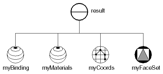
Example 5.8, “ Using Different Material Bindings ” illustrates different types of material binding using the dodecahedron created in Example 5.2, “ Creating an Indexed Face Set ” (the common code has been omitted here). The scene graph for the example is shown in Figure 5.24, “ Scene Graph for Material Binding Example ”. When you run the program, you can type a number to select the type of material binding, as follows:
0 for PER_FACE (see Figure B.7, “ Plate 7 ”)
1 for PER_VERTEX_INDEXED (see Figure B.8, “ Plate 8 ”)
2 for PER_FACE_INDEXED (see Figure B.9, “ Plate 9 ”)
Example 5.8. Using Different Material Bindings
C++// Which material to use to color the faces // half red & half blue static long materialIndices[12] = { 0, 0, 0, 0, 0, 0, 1, 1, 1, 1, 1, 1, }; switch(whichBinding) { case 0: // Set up binding to use a different color for each face myBinding->value = SoMaterialBinding::PER_FACE; break; case 1: // Set up binding to use a different color at each // vertex, BUT, vertices shared between faces will // have the same color. myBinding->value = SoMaterialBinding::PER_VERTEX_INDEXED; break; case 2: myBinding->value = SoMaterialBinding::PER_FACE_INDEXED; myIndexedFaceSet->materialIndex.setValues(0, 12, materialIndices); break; }
.NET// Which material to use to color the faces // half red & half blue static int[] materialIndices = new int[12] { 0, 0, 0, 0, 0, 0, 1, 1, 1, 1, 1, 1, }; switch(whichBinding) { case 0: // Set up binding to use a different color for each face myBinding.value.SetValue((int)SoMaterialBinding.Bindings.PER_FACE); break; case 1: // Set up binding to use a different color at each // vertex, BUT, vertices shared between faces will // have the same color. myBinding.value.SetValue((int)SoMaterialBinding.Bindings.PER_VERTEX_INDEXED); break; case 2: myBinding.value.SetValue((int)SoMaterialBinding.Bindings.PER_FACE_INDEXED); myIndexedFaceSet.materialIndex.SetValues(0, materialIndices); break; }
Java// Which material to use to color the faces // half red & half blue int[] materialIndices = new int[] { 0, 0, 0, 0, 0, 0, 1, 1, 1, 1, 1, 1, }; switch(whichBinding) { case 0: // Set up binding to use a different color for each face myBinding.value.setValue(SoMaterialBinding.Bindings.PER_FACE); break; case 1: // Set up binding to use a different color at each // vertex, BUT, vertices shared between faces will // have the same color. myBinding.value.setValue(SoMaterialBinding.Bindings.PER_VERTEX_INDEXED); break; case 2: myBinding.value.setValue(SoMaterialBinding.Bindings.PER_FACE_INDEXED); myIndexedFaceSet.materialIndex.setValues(0, materialIndices); break; }
Normals are bound to shapes in almost the same manner as materials. The type of normal binding specified in an SoNormalBinding( C++ | Java | .NET ) node is a hint to the shape node about how to apply the current normals to that shape. Indexed shape nodes such asSoIndexedFaceSet( C++ | Java | .NET )and SoIndexedTriangle- StripSet contain a normalIndex field used to store indices into the normals list (in an SoNormal( C++ | Java | .NET ) node). If the type of binding specified does not require indices (for example, PER_VERTEX), the normalIndex field is not used.
The main difference between indexed normals and indexed materials is that indexed normals do not cycle. If used, normals must match up exactly with the faces, vertices, or parts of the object. If the normals do not match exactly, then default normals are generated (see the following section). You must specify enough normals to bind to faces, parts, or vertices.
Normals can be generated automatically for any shape derived from SoVertexShape( C++ | Java | .NET ). Because this process involves a great deal of computation, we recommend that you use automatic caching or explicitly turn on render caching so that the results are saved and can be reused (see Chapter 8, Applying Actions for more information on caching). Inventor generates normals automatically if needed for rendering and
DEFAULT normal binding is used and
You do not specify any normals or the number of normals is different from the number of vertices
When Inventor generates normals automatically, it looks at the creaseAngle field of the SoShapeHints( C++ | Java | .NET ) node. The crease angle is defined as the angle between the normals for two adjoining faces. This angle indicates the maximum angle size at which separate normals are drawn for adjoining faces. For example, if the crease angle is one radian and the normals for two adjoining faces form an angle less than or equal to one radian, the faces share the same normal, which causes the edge to be shaded smoothly. If the normals for the faces form an angle greater than one radian, Inventor calculates separate normals for each face, which creates a crease. If you want an object to appear sharply faceted, specify 0 as the creaseAngle. If you want an object to appear completely smooth, specify PI as the creaseAngle.