Complex shapes, such as triangle strip sets and face sets, require at least a set of coordinates. If the lighting is set to PHONG, complex shapes also require a set of surface normals, as shown in Figure 5.2, “ Nodes Used to Create a Simple Indexed Face Set ”. Coordinates and normals are defined by separate nodes in the scene graph so that this information can be shared by other nodes.
Examples of complex shapes include the following:
Face set, indexed face set
Line set, indexed line set
Triangle strip set, indexed triangle strip set
Point set
Quad mesh
NURBS curve and surface
An SoCoordinate3( C++ | Java | .NET ) node sets the current coordinates in the rendering state to the specified points. This node contains one field (point), which is of type SoMFVec3f( C++ | Java | .NET ). For example:
C++
SbVec3f 				verts[6];
SoCoordinate3			 *coord = new SoCoordinate3;
// ...Initialize vertices array ...
coord->point.setValues(0, 6, verts);
.NET
SbVec3f[] verts = new SbVec3f[6];
SoCoordinate3	coord = new SoCoordinate3();
// ...Initialize vertices array ...
coord.point.SetValues(0, verts);
Java
SbVec3f[] verts = new SbVec3f[6];
SoCoordinate3	coord = new SoCoordinate3();
// ...Initialize vertices array ...
coord.point.setValues(0, verts);
An SoNormal( C++ | Java | .NET ) node sets the current surface normals in the rendering state to the specified vectors. This node contains one field, vector, of type SoMFVec3f( C++ | Java | .NET ).
![[Tip]](../images/tip.jpg) | |
Tip: Normals can also be generated automatically by Inventor, in which case you do not need an SoNormal( C++ | Java | .NET ) node. See the section called “Generating Normals Automatically” for further information. |
An SoFaceSet( C++ | Java | .NET ) is a shape node that represents a polygonal object formed by constructing faces out of the current coordinates, current normals, current materials, and current textures. It uses the values within each node in the order they are given. (To use coordinates, normals, and materials in a different order, use the SoIndexedFaceSet( C++ | Java | .NET ) node, described in the next section.)
Example 5.1, “ Creating a Face Set ” creates an obelisk using a face set composed of eight faces. The scene graph for this example is shown in Figure 5.3, “ Scene Graph for Face Set Example ”. Ignore the normal binding node for now. This node is explained in Section 5.4, “Binding Nodes”Figure 5.4, “ Face-Set Example”shows the image created by this example.
Example 5.1. Creating a Face Set
C++
//  Eight polygons. The first four are triangles
//  The second four are quadrilaterals for the sides.
static float vertices[28][3] =
{
   { 0, 30, 0}, {-2,27, 2}, { 2,27, 2},            //front tri
   { 0, 30, 0}, {-2,27,-2}, {-2,27, 2},            //left  tri
   { 0, 30, 0}, { 2,27,-2}, {-2,27,-2},            //rear  tri
   { 0, 30, 0}, { 2,27, 2}, { 2,27,-2},            //right tri
   {-2, 27, 2}, {-4,0, 4}, { 4,0, 4}, { 2,27, 2},  //front quad
   {-2, 27,-2}, {-4,0,-4}, {-4,0, 4}, {-2,27, 2},  //left  quad
   { 2, 27,-2}, { 4,0,-4}, {-4,0,-4}, {-2,27,-2},  //rear  quad
   { 2, 27, 2}, { 4,0, 4}, { 4,0,-4}, { 2,27,-2}   //right quad
};

// Number of vertices in each polygon:
static long numvertices[8] = {3, 3, 3, 3, 4, 4, 4, 4};

// Normals for each polygon:
static float norms[8][3] =
{
   {0, .555,  .832}, {-.832, .555, 0}, //front, left tris
   {0, .555, -.832}, { .832, .555, 0}, //rear, right tris
   {0, .0739,  .9973}, {-.9972, .0739, 0},//front, left quads
   {0, .0739, -.9973}, { .9972, .0739, 0},//rear, right quads
};

SoSeparator *
makeObeliskFaceSet()
{
   SoSeparator *obelisk = new SoSeparator();
   obelisk->ref();

   // Define the normals used:
   SoNormal *myNormals = new SoNormal;
   myNormals->vector.setValues(0, 8, norms);
   obelisk->addChild(myNormals);
   SoNormalBinding *myNormalBinding = new SoNormalBinding;
   myNormalBinding->value = SoNormalBinding::PER_FACE;
   obelisk->addChild(myNormalBinding);

   // Define material for obelisk
   SoMaterial *myMaterial = new SoMaterial;
   myMaterial->diffuseColor.setValue(.4, .4, .4);
   obelisk->addChild(myMaterial);

   // Define coordinates for vertices
   SoCoordinate3 *myCoords = new SoCoordinate3;
   myCoords->point.setValues(0, 28, vertices);
   obelisk->addChild(myCoords);

   // Define the FaceSet
   SoFaceSet *myFaceSet = new SoFaceSet;
   myFaceSet->numVertices.setValues(0, 8, numvertices);
   obelisk->addChild(myFaceSet);

   obelisk->unrefNoDelete();
   return obelisk;
}
.NET
//  Eight polygons. The first four are triangles
//  The second four are quadrilaterals for the sides.
float[,]
vertices = new float[28, 3] {
    { 0.0f, 30.0f, 0.0f}, {-2.0f,27.0f, 2.0f}, { 2.0f,27.0f, 2.0f}, // front tri
    { 0.0f, 30.0f, 0.0f}, {-2.0f,27.0f,-2.0f}, {-2.0f,27.0f, 2.0f}, // left  tri
    { 0.0f, 30.0f, 0.0f}, { 2.0f,27.0f,-2.0f}, {-2.0f,27.0f,-2.0f}, // rear  tri
    { 0.0f, 30.0f, 0.0f}, { 2.0f,27.0f, 2.0f}, { 2.0f,27.0f,-2.0f}, // right tri
    {-2.0f, 27.0f, 2.0f}, {-4.0f, 0.0f, 4.0f},
    { 4.0f,  0.0f, 4.0f}, { 2.0f,27.0f, 2.0f}, // front quad
    {-2.0f, 27.0f,-2.0f}, {-4.0f, 0.0f,-4.0f},
    {-4.0f,  0.0f, 4.0f}, {-2.0f,27.0f, 2.0f}, // left  quad
    { 2.0f, 27.0f,-2.0f}, { 4.0f, 0.0f,-4.0f},
    {-4.0f,  0.0f,-4.0f}, {-2.0f,27.0f,-2.0f}, // rear  quad
    { 2.0f, 27.0f, 2.0f}, { 4.0f, 0.0f, 4.0f},
    { 4.0f,  0.0f,-4.0f}, { 2.0f,27.0f,-2.0f}  // right quad
};

// Number of vertices in each polygon:
Int32[] numvertices = new Int32[8] { 3, 3, 3, 3, 4, 4, 4, 4 };

// Normals for each polygon:
float[,] norms = new float[8, 3] {
    {0.0f, 0.555f, 0.832f}, {-0.832f, 0.555f, 0.0f}, // front, left tris
    {0.0f, 0.555f,-0.832f}, { 0.832f, 0.555f, 0.0f}, // rear, right tris

    {0.0f, 0.0739f, 0.9973f}, {-0.9972f, 0.0739f, 0.0f}, // front, left quads
    {0.0f, 0.0739f,-0.9973f}, { 0.9972f, 0.0739f, 0.0f}, // rear, right quads
};

SoSeparator MakeObeliskFaceSet()
{
    SoSeparator obelisk = new SoSeparator();

    // Using the new SoVertexProperty node is more efficient
    SoVertexProperty myVertexProperty = new SoVertexProperty();

    // Define the normals used:
    myVertexProperty.normal.SetValues(0, 8, norms);
    myVertexProperty.normalBinding.Value = SoNormalBinding.Bindings.PER_FACE;

    // Define material for obelisk
    myVertexProperty.orderedRGBA.SetValue(new SbColor(0.4f, 0.4f, 0.4f).GetPackedValue());

    // Define coordinates for vertices
    myVertexProperty.vertex.SetValues(0, 28, vertices);

    // Define the FaceSet
    SoFaceSet myFaceSet = new SoFaceSet();
    myFaceSet.numVertices.SetValues(0, numvertices);

    myFaceSet.vertexProperty.Value = myVertexProperty;
    obelisk.AddChild(myFaceSet);

    return obelisk;
}
Java
//Eight polygons. The first four are triangles
//The second four are quadrilaterals for the sides.
float[][] vertices = new float[][] {
  { 0.0f, 30.0f, 0.0f}, {-2.0f,27.0f, 2.0f}, { 2.0f,27.0f, 2.0f}, // front tri
  { 0.0f, 30.0f, 0.0f}, {-2.0f,27.0f,-2.0f}, {-2.0f,27.0f, 2.0f}, // left  tri
  { 0.0f, 30.0f, 0.0f}, { 2.0f,27.0f,-2.0f}, {-2.0f,27.0f,-2.0f}, // rear  tri
  { 0.0f, 30.0f, 0.0f}, { 2.0f,27.0f, 2.0f}, { 2.0f,27.0f,-2.0f}, // right tri
  {-2.0f, 27.0f, 2.0f}, {-4.0f, 0.0f, 4.0f},
  { 4.0f,  0.0f, 4.0f}, { 2.0f,27.0f, 2.0f}, // front quad
  {-2.0f, 27.0f,-2.0f}, {-4.0f, 0.0f,-4.0f},
  {-4.0f,  0.0f, 4.0f}, {-2.0f,27.0f, 2.0f}, // left  quad
  { 2.0f, 27.0f,-2.0f}, { 4.0f, 0.0f,-4.0f},
  {-4.0f,  0.0f,-4.0f}, {-2.0f,27.0f,-2.0f}, // rear  quad
  { 2.0f, 27.0f, 2.0f}, { 4.0f, 0.0f, 4.0f},
  { 4.0f,  0.0f,-4.0f}, { 2.0f,27.0f,-2.0f}  // right quad
};

//Number of vertices in each polygon:
int[] numvertices = new int[] { 3, 3, 3, 3, 4, 4, 4, 4 };

//Normals for each polygon:
float[][] norms = new float[][] {
  {0.0f, 0.555f, 0.832f}, {-0.832f, 0.555f, 0.0f}, // front, left tris
  {0.0f, 0.555f,-0.832f}, { 0.832f, 0.555f, 0.0f}, // rear, right tris

  {0.0f, 0.0739f, 0.9973f}, {-0.9972f, 0.0739f, 0.0f}, // front, left quads
  {0.0f, 0.0739f,-0.9973f}, { 0.9972f, 0.0739f, 0.0f}, // rear, right quads
};

SoSeparator MakeObeliskFaceSet()
{
  SoSeparator obelisk = new SoSeparator();

  // Using the new SoVertexProperty node is more efficient
  SoVertexProperty myVertexProperty = new SoVertexProperty();

  // Define the normals used:
  myVertexProperty.normal.setValues(0, norms);
  myVertexProperty.normalBinding.setValue(SoNormalBinding.Bindings.PER_FACE);

  // Define material for obelisk
  myVertexProperty.orderedRGBA.setValue(new SbColor(0.4f, 0.4f, 0.4f).getPackedValue());

  // Define coordinates for vertices
  myVertexProperty.vertex.setValues(0, vertices);

  // Define the FaceSet
  SoFaceSet myFaceSet = new SoFaceSet();
  myFaceSet.numVertices.setValues(0, numvertices);

  myFaceSet.vertexProperty.setValue(myVertexProperty);
  obelisk.addChild(myFaceSet);

  return obelisk;
}
| |
Tip: When you construct a scene graph, be sure that you have used as few nodes as possible to accomplish your goals. For example, to create a multifaceted polygonal shape, it's best to put all the coordinates for the shape into one SoCoordinate node and put the description of all the face sets into a single SoFaceSet( C++ | Java | .NET ) (or SoIndexedFaceSet( C++ | Java | .NET )) node rather than using multiple nodes for each face. |
An SoIndexedFaceSet( C++ | Java | .NET ) node is a shape node that represents a polygonal object formed by constructing faces out of the current coordinates, using the current surface normals, current materials, and current texture. In contrast to the SoFaceSet( C++ | Java | .NET ) node, this node can use those values in any order. This node class contains four fields with indices that specify the ordering:
coordIndex (SoMFLong) | contains indices into the coordinates list. These indices connect coordinates to form a set of faces. A value of SO_END_FACE_INDEX (-1) indicates the end of one face and the start of the next face. This field is always used. |
materialIndex (SoMFLong) | contains indices into the current material(s) for the materials of the face set. This field is used only when some type of indexed material binding is specified in the SoMaterialBinding( C++ | Java | .NET ) node. See Section 5.4, “Binding Nodes”. |
normalIndex (SoMFLong) | contains indices into the current normals for the vertices of the face set. This field is used only when indexed normal binding (either per vertex or per face) is specified in the SoNormalBinding( C++ | Java | .NET ) node. See Section 5.4, “Binding Nodes”. |
textureCoordIndex (SoMFLong) | contains indices of the texture coordinates that are applied to the shape (see Chapter 7, Textures). |
Be sure that the indices contained in the indexed face set can actually be found in the coordinates and normals lists, or errors will occur.
![[Note]](../images/note.jpg) | |
Note: If you use the SoShapeHints( C++ | Java | .NET ) node to specify that the vertices are counterclockwise, you must specify the vertex indices according to the right-hand rule. The right-hand rule states that if you place the fingers of your right hand around the face following the direction in which the vertices are specified, your thumb points in the general direction of the geometric normal. Alternatively, you can specify the vertices in clockwise order. In this case, the direction of the geometric normal is determined by the left-hand rule. |
Example 5.2, “ Creating an Indexed Face Set ” creates the first stellation of the dodecahedron from an indexed face set. Each of the twelve intersecting faces is a pentagon. The scene graph diagram for this example is shown in Figure 5.5, “ Scene Graph for Indexed Face-Set Example ”. Figure 5.6, “ Indexed Face-Set Example” shows the image created by this example.
Example 5.2. Creating an Indexed Face Set
C++
// Positions of all of the vertices:
static float vertexPositions[12][3] =
{
   { 0.0000,  1.2142,  0.7453},  // top

   { 0.0000,  1.2142, -0.7453},  // points surrounding top
   {-1.2142,  0.7453,  0.0000},
   {-0.7453,  0.0000,  1.2142},
   { 0.7453,  0.0000,  1.2142},
   { 1.2142,  0.7453,  0.0000},

   { 0.0000, -1.2142,  0.7453},  // points surrounding bottom
   {-1.2142, -0.7453,  0.0000},
   {-0.7453,  0.0000, -1.2142},
   { 0.7453,  0.0000, -1.2142},
   { 1.2142, -0.7453,  0.0000},

   { 0.0000, -1.2142, -0.7453}, // bottom
};
.NET
// Positions of all of the vertices:
float[,] vertexPositions = new float[12, 3] {
    { 0.0000f,  1.2142f,  0.7453f},  // top

    { 0.0000f,  1.2142f, -0.7453f},  // points surrounding top
    {-1.2142f,  0.7453f,  0.0000f},
    {-0.7453f,  0.0000f,  1.2142f},
    { 0.7453f,  0.0000f,  1.2142f},
    { 1.2142f,  0.7453f,  0.0000f},

    { 0.0000f, -1.2142f,  0.7453f},  // points surrounding bottom
    {-1.2142f, -0.7453f,  0.0000f},
    {-0.7453f,  0.0000f, -1.2142f},
    { 0.7453f,  0.0000f, -1.2142f},
    { 1.2142f, -0.7453f,  0.0000f},

    { 0.0000f, -1.2142f, -0.7453f}, // bottom
};
Java
//Positions of all of the vertices:
float[][] vertexPositions = new float[][] {
    { 0.0000f,  1.2142f,  0.7453f},  // top

    { 0.0000f,  1.2142f, -0.7453f},  // points surrounding top
    {-1.2142f,  0.7453f,  0.0000f},
    {-0.7453f,  0.0000f,  1.2142f},
    { 0.7453f,  0.0000f,  1.2142f},
    { 1.2142f,  0.7453f,  0.0000f},

    { 0.0000f, -1.2142f,  0.7453f},  // points surrounding bottom
    {-1.2142f, -0.7453f,  0.0000f},
    {-0.7453f,  0.0000f, -1.2142f},
    { 0.7453f,  0.0000f, -1.2142f},
    { 1.2142f, -0.7453f,  0.0000f},

    { 0.0000f, -1.2142f, -0.7453f}, // bottom
};
C++
// Connectivity, information; 12 faces with 5 vertices each },
// (plus the end-of-face indicator for each face):

static long indices[72] =
{
    1, 2,  3,  4, 5, SO_END_FACE_INDEX, // top face

    0, 1,  8,  7, 3, SO_END_FACE_INDEX, // 5 faces about top
    0, 2,  7,  6, 4, SO_END_FACE_INDEX,
    0, 3,  6, 10, 5, SO_END_FACE_INDEX,
    0, 4, 10,  9, 1, SO_END_FACE_INDEX,
    0, 5,  9,  8, 2, SO_END_FACE_INDEX,

    9,  5, 4, 6, 11, SO_END_FACE_INDEX, // 5 faces about bottom
   10,  4, 3, 7, 11, SO_END_FACE_INDEX,
    6,  3, 2, 8, 11, SO_END_FACE_INDEX,
    7,  2, 1, 9, 11, SO_END_FACE_INDEX,
    8,  1, 5,10, 11, SO_END_FACE_INDEX,

    6,  7, 8, 9, 10, SO_END_FACE_INDEX, // bottom face
};

// Colors for the 12 faces
static float colors[12][3] =
{
   {1.0, .0, 0}, { .0,  .0, 1.0}, {0, .7,  .7}, { .0, 1.0,  0},
   { .7, .7, 0}, { .7,  .0,  .7}, {0, .0, 1.0}, { .7,  .0, .7},
   { .7, .7, 0}, { .0, 1.0,  .0}, {0, .7,  .7}, {1.0,  .0,  0}
};

// Routine to create a scene graph representing a dodecahedron
SoSeparator *
makeStellatedDodecahedron()
{
   SoSeparator *result = new SoSeparator;
   result->ref();

   // Define colors for the faces
   SoMaterial *myMaterials = new SoMaterial;
   myMaterials->diffuseColor.setValues(0, 12, colors);
   result->addChild(myMaterials);
   SoMaterialBinding *myMaterialBinding = new SoMaterialBinding;
   myMaterialBinding->value = SoMaterialBinding::PER_FACE;
   result->addChild(myMaterialBinding);

   // Define coordinates for vertices

   // Define coordinates for vertices
   SoCoordinate3 *myCoords = new SoCoordinate3;
   myCoords->point.setValues(0, 12, vertexPositions);
   result->addChild(myCoords);

   // Define the IndexedFaceSet, with indices into the vertices:
   SoIndexedFaceSet *myFaceSet = new SoIndexedFaceSet;
   myFaceSet->coordIndex.setValues(0, 72, indices);
   result->addChild(myFaceSet);

   result->unrefNoDelete();
   return result;
}
.NET
// Connectivity, information; 12 faces with 5 vertices each },
// (plus the end-of-face indicator for each face):

Int32[] indices = new Int32[72]
{
    1, 2, 3, 4, 5, -1, // top face

    0, 1, 8, 7, 3, -1, // 5 faces about top
    0, 2, 7, 6, 4, -1,
    0, 3, 6,10, 5, -1,
    0, 4,10, 9, 1, -1,
    0, 5, 9, 8, 2, -1,

    9, 5, 4, 6,11, -1, // 5 faces about bottom
   10, 4, 3, 7,11, -1,
    6, 3, 2, 8,11, -1,
    7, 2, 1, 9,11, -1,
    8, 1, 5,10,11, -1,

    6, 7, 8, 9,10, -1, // bottom face
};

// Colors for the 12 faces
float[,] colors = new float[12, 3]
{
    { 1.0f, 0.0f, 0.0f}, { 0.0f, 0.0f, 1.0f},
    { 0.0f, 0.7f, 0.7f}, { 0.0f, 1.0f, 0.0f},
    { 0.7f, 0.7f, 0.0f}, { 0.7f, 0.0f, 0.7f},
    { 0.0f, 0.0f, 1.0f}, { 0.7f, 0.0f, 0.7f},
    { 0.7f, 0.7f, 0.0f}, { 0.0f, 1.0f, 0.0f},
    { 0.0f, 0.7f, 0.7f}, { 1.0f, 0.0f, 0.0f}
};

// Routine to create a scene graph representing a dodecahedron
SoSeparator makeStellatedDodecahedron()
{
    SoSeparator result = new SoSeparator();

    // Using the new SoVertexProperty node is more efficient
    SoVertexProperty myVertexProperty = new SoVertexProperty();

    // Define colors for the faces
    for (int i = 0; i < 12; i++)
        myVertexProperty.orderedRGBA[i] =
          new SbColor(colors[i, 0], colors[i, 1], colors[i, 2]).GetPackedValue();
    myVertexProperty.materialBinding.Value = SoMaterialBinding.Bindings.PER_FACE;

    // Define coordinates for vertices
    myVertexProperty.vertex.SetValues(0, 12, vertexPositions);

    // Define the IndexedFaceSet, with indices into
    // the vertices:
    SoIndexedFaceSet myFaceSet = new SoIndexedFaceSet();
    myFaceSet.coordIndex.SetValues(0, indices);

    myFaceSet.vertexProperty.Value = myVertexProperty;
    result.AddChild(myFaceSet);

    return result;
}
Java
//Connectivity, information; 12 faces with 5 vertices each },
//(plus the end-of-face indicator for each face):

int[] indices = new int[]
{
   1, 2, 3, 4, 5, -1, // top face

   0, 1, 8, 7, 3, -1, // 5 faces about top
   0, 2, 7, 6, 4, -1,
   0, 3, 6,10, 5, -1,
   0, 4,10, 9, 1, -1,
   0, 5, 9, 8, 2, -1,

   9, 5, 4, 6,11, -1, // 5 faces about bottom
  10, 4, 3, 7,11, -1,
   6, 3, 2, 8,11, -1,
   7, 2, 1, 9,11, -1,
   8, 1, 5,10,11, -1,

   6, 7, 8, 9,10, -1, // bottom face
};

//Colors for the 12 faces
float[][] colors = new float[][]
{
   { 1.0f, 0.0f, 0.0f}, { 0.0f, 0.0f, 1.0f},
   { 0.0f, 0.7f, 0.7f}, { 0.0f, 1.0f, 0.0f},
   { 0.7f, 0.7f, 0.0f}, { 0.7f, 0.0f, 0.7f},
   { 0.0f, 0.0f, 1.0f}, { 0.7f, 0.0f, 0.7f},
   { 0.7f, 0.7f, 0.0f}, { 0.0f, 1.0f, 0.0f},
   { 0.0f, 0.7f, 0.7f}, { 1.0f, 0.0f, 0.0f}
};

//Routine to create a scene graph representing a dodecahedron
SoSeparator makeStellatedDodecahedron()
{
   SoSeparator result = new SoSeparator();

   // Using the new SoVertexProperty node is more efficient
   SoVertexProperty myVertexProperty = new SoVertexProperty();

   // Define colors for the faces
   for (int i = 0; i < 12; i++)
       myVertexProperty.orderedRGBA.set1Value(i,
             new SbColor(colors[i][0], colors[i][1], colors[i][2]).getPackedValue());
   myVertexProperty.materialBinding.setValue(SoMaterialBinding.Bindings.PER_FACE);

   // Define coordinates for vertices
   myVertexProperty.vertex.setValues(0, 12, vertexPositions);

   // Define the IndexedFaceSet, with indices into
   // the vertices:
   SoIndexedFaceSet myFaceSet = new SoIndexedFaceSet();
   myFaceSet.coordIndex.setValues(0, indices);

   myFaceSet.vertexProperty.setValue(myVertexProperty);
   result.addChild(myFaceSet);

   return result;
}
Polygons with holes can be described efficiently as a set of “contours” (boundary edges) in SoFaceSet( C++ | Java | .NET )and SoIndexedFaceSet( C++ | Java | .NET ). The SoShapeHints( C++ | Java | .NET ) windingType field allows you to specify how the interior and exterior regions of a polygon are determined. These classes expose the full power of the GLU tessellator.
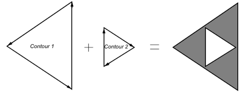
In the previous picture, two contours are specified. A winding type was chosen such that contour 2 defines a hole.
There are some basic concepts that you must know before creating holes with SoIndexedFaceSet( C++ | Java | .NET )or SoFaceSet( C++ | Java | .NET )shapes. Most important, to create a hole in a surface, you must insert an SoShapeHints( C++ | Java | .NET )node before the SoIndexedFaceSet( C++ | Java | .NET )or the SoFaceSet( C++ | Java | .NET )node.
![[Warning]](../images/warning.jpg) | |
The windingType field of SoShapeHints( C++ | Java | .NET ) was introduced in Open Inventor 4.0. If you specify a non-default value for the windingType field, when this node is written to an Inventor file, the file will contain this new field. Older versions of Open Inventor (before version 4.0) will not be able to read this file and will generate an Inventor read error (unknown field). |
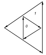
For a single contour, the winding number of a point is the signed number of revolutions we make around that point while traveling once around the contour (where a counterclockwise revolution is positive and a clockwise revolution is negative). When there are several contours, the individual winding numbers are summed. In the following picture on the left, all three contours are counterclockwise, so each nested interior region adds one to the winding number.
In the picture on the right, the two interior contours are drawn clockwise, so the winding number decreases and actually becomes negative.
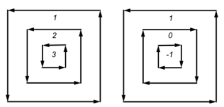
Knowing the winding numbers of the regions of your face, you can select a winding type to produce the desired results.
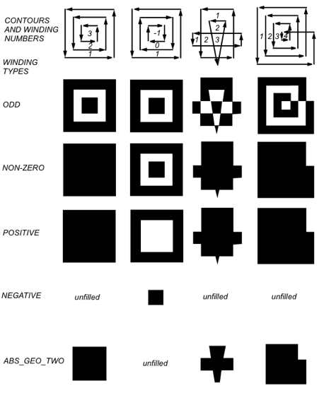
The winding types classify a region as interior if its winding number belongs to the chosen category.
We must add code (before the SoIndexedFaceSet( C++ | Java | .NET )or SoFaceSet( C++ | Java | .NET ) ) to specify the winding type we want to use. For example,
C++
m_hints = new SoShapeHints;
root->addChild(m_hints);
// If we want to use an ODD winding type.
m_hints->windingType=SoShapeHints::ODD_TYPE;
.NET
SoShapeHints m_hints = new SoShapeHints();
root.AddChild(m_hints);
// If we want to use an ODD winding type.
m_hints.windingType.SetValue((int)SoShapeHints.WindingTypes.ODD_TYPE);
Java
SoShapeHints m_hints = new SoShapeHints();
root.addChild(m_hints);
// If we want to use an ODD winding type.
m_hints.windingType.setValue(SoShapeHints.WindingTypes.ODD_TYPE);
Now, we must integrate this code with the SoIndexedFaceSet( C++ | Java | .NET )or the SoFaceSet( C++ | Java | .NET )shapes.
Create a list of coordinates for the contours you will use. (See SoIndexedFaceSet( C++ | Java | .NET )in the Reference Manual.)
Example:
C++static const float vertexPositions[7][3] = { {0, 0, 0}, { 1, 1, 0 } , { 1, 0, 0 } , { 1,-1, 0 }, {0.3f, 0.2f, 0}, { 0.8f, 0, 0 } , { 0.3f, -0.2f, 0 } };
.NETstatic const float[,] vertexPositions = new float[7,3] { {0, 0, 0}, { 1, 1, 0 } , { 1, 0, 0 } , { 1,-1, 0 }, {0.3f, 0.2f, 0}, { 0.8f, 0, 0 } , { 0.3f, -0.2f, 0 } };
Javastatic float[][] vertexPositions = new float[][] { {0, 0, 0}, { 1, 1, 0 } , { 1, 0, 0 } , { 1,-1, 0 }, {0.3f, 0.2f, 0}, { 0.8f, 0, 0 } , { 0.3f, -0.2f, 0 } };Now we define indices for the outer contour and the contour that will define the hole.
Example:
C++static int32_t indices[8] = { 0, 3, 1, SO_END_CONTOUR_INDEX, // Outer contour 5, 6, 4, SO_END_CONTOUR_INDEX // Hole contour };
.NETpublic static int[] indices= new int[8] { 0, 3, 1, -1, // Outer contour 5, 6, 4, -1 // Hole contour };
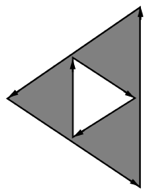
Javapublic static int[] indices= new int[] { 0, 3, 1, -1, // Outer contour 5, 6, 4, -1 // Hole contour };Figure 5.10, “Winding numbers defining a hole” shows the winding numbers for the different regions of the polygon (see the section called “Winding Numbers”). The centermost region has a winding number of 0 because the first contour is counterclockwise, and the interior one is clockwise.
As you can see, we have defined two contours. The first one is the outer contour and the second one is the definition of the hole.
Now we have to decide what winding type we are going to use (see the section called “Winding type”):
Here are results we will get in our example with the following winding types:
For ODD, NON_ZERO, and POSITIVE: See Figure 5.11, “ODD, NON_ZERO, and POSITIVE winding types”.
For NEGATIVE and ABS_GEQ_TWO: Unfilled.
For NO_WINDING: Two distinct but coplanar surfaces.
To describe this in Open Inventor we must add the following code before the definition of the SoIndexedFaceSet( C++ | Java | .NET ) :
C++m_hints = new SoShapeHints; root->addChild(m_hints); // If we want to use an ODD winding type. m_hints->windingType=SoShapeHints::ODD_TYPE;
.NETSoShapeHints m_hints = new SoShapeHints(); root.AddChild(m_hints); // If we want to use an ODD winding type. m_hints.windingType.Value = SoShapeHints.WindingTypes.ODD_TYPE;
JavaSoShapeHints m_hints = new SoShapeHints(); root.addChild(m_hints); // If we want to use an ODD winding type. m_hints.windingType.setValue(SoShapeHints.WindingTypes.ODD_TYPE);
If we forget the previous four lines, we will get two coplanar sufaces.
And now the final code will be:
C++
SoSeparator *root = new SoSeparator; root->ref(); // 1) Define the winding type to use. This code asks Open Inventor to // use the following IndexedFaceSet as contours. myShapeHints = new SoShapeHints; root->addChild(myShapeHints); // If we want to use an ODD winding type. myShapeHints->windingType=SoShapeHints::ODD_TYPE; // 2) Creation of the indexedFaceSet. SoVertexProperty *myVertexProperty = new SoVertexProperty; // Define coordinates for vertices myVertexProperty->vertex.setValues(0, 7, vertexPositions); // Define the IndexedFaceSet, with indices into the vertices: SoIndexedFaceSet *myIndexedFaceSet = new SoIndexedFaceSet; myIndexedFaceSet ->coordIndex.setValues(0, 8, indices); myIndexedFaceSet ->vertexProperty.setValue(myVertexProperty); root->addChild(myIndexedFaceSet);
.NET
SoSeparator root = new SoSeparator(); // 1) Define the winding type to use. This code asks Open Inventor to // use the following IndexedFaceSet as contours. SoShapeHints myShapeHints = new SoShapeHints(); root.AddChild(myShapeHints); // If we want to use an ODD winding type. myShapeHints.windingType.Value = SoShapeHints.WindingTypes.ODD_TYPE; // 2) Creation of the indexedFaceSet. SoVertexProperty myVertexProperty = new SoVertexProperty(); // Define coordinates for vertices myVertexProperty.vertex.SetValues(0, vertexPositions); // Define the IndexedFaceSet, with indices into the vertices: SoIndexedFaceSet myIndexedFaceSet = new SoIndexedFaceSet(); myIndexedFaceSet.coordIndex.SetValues(0, indices); myIndexedFaceSet.vertexProperty.Value = myVertexProperty; root.AddChild(myIndexedFaceSet);
Java
SoSeparator root = new SoSeparator(); // 1) Define the winding type to use. This code asks Open Inventor to // use the following IndexedFaceSet as contours. SoShapeHints myShapeHints = new SoShapeHints(); root.addChild(myShapeHints); // If we want to use an ODD winding type. myShapeHints.windingType.setValue(SoShapeHints.WindingTypes.ODD_TYPE); // 2) Creation of the indexedFaceSet. SoVertexProperty myVertexProperty = new SoVertexProperty(); // Define coordinates for vertices myVertexProperty.vertex.setValues(0, vertexPositions); // Define the IndexedFaceSet, with indices into the vertices: SoIndexedFaceSet myIndexedFaceSet = new SoIndexedFaceSet(); myIndexedFaceSet.coordIndex.setValues(0, indices); myIndexedFaceSet.vertexProperty.setValue(myVertexProperty); root.addChild(myIndexedFaceSet);
With the SoFaceSet( C++ | Java | .NET )node, there are no indices. It uses the coordinates in order, starting with the first one. Each contour has a number of vertices specified by a value in the numVertices field.
Example:
C++
static const float vertices[6][3] = { // First contour. {0, 0, 0}, {1, -1, 0}, {1, 1, 0}, // Second contour. {0.8f, 0, 0}, {0.3f, -0.2f, 0}, {0.3f, 0.2f, 0} }; // Number of vertices in each polygon: static int32_t numvertices[2] = {3, 3};
.NET
static const float[,] vertices = new float[6,3] { // First contour. {0, 0, 0}, {1, -1, 0}, {1, 1, 0}, // Second contour. {0.8f, 0, 0}, {0.3f, -0.2f, 0}, {0.3f, 0.2f, 0} }; // Number of vertices in each polygon: static int[] numvertices = new int[2]{3, 3};
Java
static float[][] vertices = new float[][]
{
// First contour.
{0, 0, 0},
{1, -1, 0},
{1, 1, 0},
// Second contour.
{0.8f, 0, 0},
{0.3f, -0.2f, 0},
{0.3f, 0.2f, 0}
};
// Number of vertices in each polygon:
static int[] numvertices = new int[]{3, 3};
Just like the previous example, the winding numbers are shown in Figure 5.10, “Winding numbers defining a hole”.
Now we must specify the winding type to use (See the section called “Winding type”), which is given by the following code:
C++
m_hints = new SoShapeHints;
root->addChild(m_hints);
// If we want to use an ODD winding type.
m_hints->windingType=SoShapeHints::ODD_TYPE;
.NET
SoShapeHints m_hints = new SoShapeHints();
root.AddChild(m_hints);
// If we want to use an ODD winding type.
m_hints.windingType.Value = SoShapeHints.WindingTypes.ODD_TYPE;
Java
SoShapeHints m_hints = new SoShapeHints();
root.addChild(m_hints);
// If we want to use an ODD winding type.
m_hints.windingType.setValue(SoShapeHints.WindingTypes.ODD_TYPE);
| |
If we forget the previous four lines, we will get get two coplanar sufaces. |
Here are results we will get in our example with following winding types:
For ODD, NON_ZERO, and POSITIVE: See Figure 5.11, “ODD, NON_ZERO, and POSITIVE winding types”.
For NEGATIVE and ABS_GEQ_TWO: Unfilled.
For NO_WINDING: Two distinct (but coplanar) faces.
The final code to create a hole with an SoFaceSet( C++ | Java | .NET )node is:
C++
SoSeparator *root = new SoSeparator;
root->ref();

// 1) Define the winding type to use. This code asks Open Inventor to
// use following IndexedFaceSet as contours.
myShapeHints = new SoShapeHints;
root->addChild(myShapeHints);
// If we want to use an ODD winding type.
myShapeHints->windingType=SoShapeHints::ODD_TYPE;

// 2) Create the SoFaceSet
// Using the new SoVertexProperty node is more efficient
SoVertexProperty *myVertexProperty = new SoVertexProperty;

// Define coordinates for vertices
myVertexProperty->vertex.setValues(0, 12, vertices);

// Define the FaceSet
SoFaceSet *myFaceSet = new SoFaceSet;
myFaceSet->numVertices.setValues(0, 4, numvertices);

myFaceSet->vertexProperty.setValue(myVertexProperty);
root->addChild(myFaceSet);
.NET
SoSeparator root = new SoSeparator();

// 1) Define the winding type to use. This code asks Open Inventor to
// use following IndexedFaceSet as contours.
SoShapeHints myShapeHints = new SoShapeHints();
root.AddChild(myShapeHints);
// If we want to use an ODD winding type.
myShapeHints.windingType.Value = SoShapeHints.WindingTypes.ODD_TYPE;

// 2) Create the SoFaceSet
// Using the new SoVertexProperty node is more efficient
SoVertexProperty myVertexProperty = new SoVertexProperty();

// Define coordinates for vertices
myVertexProperty.vertex.SetValues(0, vertices);

// Define the FaceSet
SoFaceSet myFaceSet = new SoFaceSet();
myFaceSet.numVertices.SetValues(0, numvertices);

myFaceSet.vertexProperty.Value = myVertexProperty;
root.AddChild(myFaceSet);
Java
SoSeparator root = new SoSeparator();

// 1) Define the winding type to use. This code asks Open Inventor to
// use following IndexedFaceSet as contours.
SoShapeHints myShapeHints = new SoShapeHints();
root.addChild(myShapeHints);
// If we want to use an ODD winding type.
myShapeHints.windingType.setValue(SoShapeHints.WindingTypes.ODD_TYPE);

// 2) Create the SoFaceSet
// Using the new SoVertexProperty node is more efficient
SoVertexProperty myVertexProperty = new SoVertexProperty();

// Define coordinates for vertices
myVertexProperty.vertex.setValues(0, vertices);

// Define the FaceSet
SoFaceSet myFaceSet = new SoFaceSet();
myFaceSet.numVertices.setValues(0, numvertices);

myFaceSet.vertexProperty.setValue(myVertexProperty);
root.addChild(myFaceSet);
The SoTriangleStripSet( C++ | Java | .NET ) node constructs triangle strips out of the vertices located at the current coordinates. It is one of the fastest ways to draw polygonal objects in Inventor. The triangle strip set uses the current coordinates, in order, starting at the index specified by the startIndex field. (If no index is specified, it starts at the first index.)
The numVertices field indicates the number of vertices to use for each triangle strip in the set. The triangle strip set is described as follows:
C++
static long numVertices[2] =
{
   32, // flag
   8   // pole
};
SoTriangleStripSet *myStrips = new SoTriangleStripSet;
myStrips->numVertices.setValues(0, 2, numVertices);
.NET
static int[] numVertices = new int[2]
{
   32, // flag
   8   // pole
};
SoTriangleStripSet myStrips = new SoTriangleStripSet();
myStrips.numVertices.SetValues(0, numVertices);
Java
static int[] numVertices = new int[]
{
  32, // flag
  8   // pole
};
SoTriangleStripSet myStrips = new SoTriangleStripSet();
myStrips.numVertices.setValues(0, numVertices);
Because the numVertices field contains an array with two values, two triangle strips are created. The first strip (the flag) is made from the first 32 coordinate values. The second strip (the flagpole) is made from the next 8 coordinates. Face 0 determines the vertex ordering—in this case, counterclockwise.
Example 5.3, “ Creating a Triangle Strip Set ” shows the code for creating a pennant-shaped flag. Figure 5.12, “ Scene Graph for Triangle Strip Set Example ” shows the scene graph for this example. Figure 5.13, “ Triangle Strip Set Example” shows the resulting image.
Example 5.3. Creating a Triangle Strip Set
C++
// Positions of all of the vertices:
static float vertexPositions[40][3] =
{
   {  0,   12,    0 }, {   0,   15,    0},
   {2.1, 12.1,  -.2 }, { 2.1, 14.6,  -.2},
   {  4, 12.5,  -.7 }, {   4, 14.5,  -.7},
   {4.5, 12.6,  -.8 }, { 4.5, 14.4,  -.8},
   {  5, 12.7,   -1 }, {   5, 14.4,   -1},
   {4.5, 12.8, -1.4 }, { 4.5, 14.6, -1.4},
   {  4, 12.9, -1.6 }, {   4, 14.8, -1.6},
   {3.3, 12.9, -1.8 }, { 3.3, 14.9, -1.8},
   {  3,   13, -2.0 }, {   3, 14.9, -2.0},
   {3.3, 13.1, -2.2 }, { 3.3, 15.0, -2.2},
   {  4, 13.2, -2.5 }, {   4, 15.0, -2.5},
   {  6, 13.5, -2.2 }, {   6, 14.8, -2.2},
   {  8, 13.4,   -2 }, {   8, 14.6,   -2},
   { 10, 13.7, -1.8 }, {  10, 14.4, -1.8},
   { 12,   14, -1.3 }, {  12, 14.5, -1.3},
   { 15, 14.9, -1.2 }, {  15,   15, -1.2},

   {-.5, 15,   0 }, { -.5, 0,   0},   // the flagpole
   {  0, 15,  .5 }, {   0, 0,  .5},
   {  0, 15, -.5 }, {   0, 0, -.5},
   {-.5, 15,   0 }, { -.5, 0,   0}
};


// Number of vertices in each strip.
static long numVertices[2] =
{
   32, // flag
   8   // pole
};

// Colors for the 12 faces
static float colors[2][3] =
{
   { .5, .5,  1 }, // purple flag
   { .4, .4, .4 }, // grey flagpole
};

// Routine to create a scene graph representing a pennant.
SoSeparator *
makePennant()
{
  SoSeparator *result = new SoSeparator;
  result->ref();

  // A shape hints tells the ordering of polygons.
  // This ensures double-sided lighting.
  SoShapeHints *myHints = new SoShapeHints;
  myHints->vertexOrdering = SoShapeHints::COUNTERCLOCKWISE;
  result->addChild(myHints);

  // Define colors for the strips
  SoMaterial *myMaterials = new SoMaterial;
  myMaterials->diffuseColor.setValues(0, 2, colors);
  result->addChild(myMaterials);
  SoMaterialBinding *myMaterialBinding = new SoMaterialBinding;
  myMaterialBinding->value = SoMaterialBinding::PER_PART;
  result->addChild(myMaterialBinding);

  // Define coordinates for vertices
  SoCoordinate3 *myCoords = new SoCoordinate3;
  myCoords->point.setValues(0, 40, vertexPositions);
  result->addChild(myCoords);

  // Define the TriangleStripSet, made of two strips.
  SoTriangleStripSet *myStrips = new SoTriangleStripSet;
  myStrips->numVertices.setValues(0, 2, numVertices);
  result->addChild(myStrips);

  result->unrefNoDelete();
  return result;
}
.NET
// Positions of all of the vertices:
float[,] vertexPositions = new float[40, 3]
{
  { 0.0f,12.0f, 0.0f }, { 0.0f,15.0f, 0.0f},
  { 2.1f,12.1f,-0.2f }, { 2.1f,14.6f,-0.2f},
  { 4.0f,12.5f,-0.7f }, { 4.0f,14.5f,-0.7f},
  { 4.5f,12.6f,-0.8f }, { 4.5f,14.4f,-0.8f},
  { 5.0f,12.7f,-1.0f }, { 5.0f,14.4f,-1.0f},
  { 4.5f,12.8f,-1.4f }, { 4.5f,14.6f,-1.4f},
  { 4.0f,12.9f,-1.6f }, { 4.0f,14.8f,-1.6f},
  { 3.3f,12.9f,-1.8f }, { 3.3f,14.9f,-1.8f},
  { 3.0f,13.0f,-2.0f }, { 3.0f,14.9f,-2.0f},
  { 3.3f,13.1f,-2.2f }, { 3.3f,15.0f,-2.2f},
  { 4.0f,13.2f,-2.5f }, { 4.0f,15.0f,-2.5f},
  { 6.0f,13.5f,-2.2f }, { 6.0f,14.8f,-2.2f},
  { 8.0f,13.4f,-2.0f }, { 8.0f,14.6f,-2.0f},
  {10.0f,13.7f,-1.8f }, {10.0f,14.4f,-1.8f},
  {12.0f,14.0f,-1.3f }, {12.0f,14.5f,-1.3f},
  {15.0f,14.9f,-1.2f }, {15.0f,15.0f,-1.2f},

  {-0.5f,15.0f, 0.0f }, {-0.5f, 0.0f, 0.0f},   // the flagpole
  { 0.0f,15.0f, 0.5f }, { 0.0f, 0.0f, 0.5f},
  { 0.0f,15.0f,-0.5f }, { 0.0f, 0.0f,-0.5f},
  {-0.5f,15.0f, 0.0f }, {-0.5f, 0.0f, 0.0f}
};

// Number of vertices in each strip.
Int32[] numVertices = new Int32[2]
{
  32, // flag
  8   // pole
};

// Colors for the 12 faces
float[,] colors = new float[2, 3]
{
  { 0.5f, 0.5f, 1.0f }, // purple flag
  { 0.4f, 0.4f, 0.4f }, // grey flagpole
};

// Routine to create a scene graph representing a pennant.
SoSeparator MakePennant()
{
  SoSeparator result = new SoSeparator();

  // A shape hints tells the ordering of polygons.
  // This insures double sided lighting.
  SoShapeHints myHints = new SoShapeHints();
  myHints.vertexOrdering.Value = SoShapeHints.VertexOrderings.COUNTERCLOCKWISE;
  result.AddChild(myHints);

  // Using the new SoVertexProperty node is more efficient
  SoVertexProperty myVertexProperty = new SoVertexProperty();

  // Define colors for the strips
  for (int i = 0; i < 2; i++)
      myVertexProperty.orderedRGBA[i] =
        new SbColor(colors[i, 0], colors[i, 1], colors[i, 2]).GetPackedValue();
  myVertexProperty.materialBinding.Value = SoMaterialBinding.Bindings.PER_PART;

  // Define coordinates for vertices
  myVertexProperty.vertex.SetValues(0, 40, vertexPositions);

  // Define the TriangleStripSet, made of two strips.
  SoTriangleStripSet myStrips = new SoTriangleStripSet();
  myStrips.numVertices.SetValues(0, numVertices);

  myStrips.vertexProperty.Value = myVertexProperty;
  result.AddChild(myStrips);

  return result;
}
Java
// Positions of all of the vertices:
static float vertexPositions[][] =
{
  {  0F,   12F,    0F }, {   0F,   15F,    0F},
  {2.1F, 12.1F,  -.2F }, { 2.1F, 14.6F,  -.2F},
  {  4F, 12.5F,  -.7F }, {   4F, 14.5F,  -.7F},
  {4.5F, 12.6F,  -.8F }, { 4.5F, 14.4F,  -.8F},
  {  5F, 12.7F,   -1F }, {   5F, 14.4F,   -1F},
  {4.5F, 12.8F, -1.4F }, { 4.5F, 14.6F, -1.4F},
  {  4F, 12.9F, -1.6F }, {   4F, 14.8F, -1.6F},
  {3.3F, 12.9F, -1.8F }, { 3.3F, 14.9F, -1.8F},
  {  3F,   13F, -2.0F }, {   3F, 14.9F, -2.0F},
  {3.3F, 13.1F, -2.2F }, { 3.3F, 15.0F, -2.2F},
  {  4F, 13.2F, -2.5F }, {   4F, 15.0F, -2.5F},
  {  6F, 13.5F, -2.2F }, {   6F, 14.8F, -2.2F},
  {  8F, 13.4F,   -2F }, {   8F, 14.6F,   -2F},
  { 10F, 13.7F, -1.8F }, {  10F, 14.4F, -1.8F},
  { 12F,   14F, -1.3F }, {  12F, 14.5F, -1.3F},
  { 15F, 14.9F, -1.2F }, {  15F,   15F, -1.2F},

  {-.5F, 15F,   0F }, { -.5F, 0F,   0F},   // the flagpole
  {  0F, 15F,  .5F }, {   0F, 0F,  .5F},
  {  0F, 15F, -.5F }, {   0F, 0F, -.5F},
  {-.5F, 15F,   0F }, { -.5F, 0F,   0F}
};

// Number of vertices in each strip.
static int numVertices[] =
{
  32, // flag
  8   // pole
};

// Colors for the 12 faces
static float colors[][] =
{
  { .5F, .5F,  1F }, // purple flag
  { .4F, .4F, .4F } // grey flagpole
};

// Routine to create a scene graph representing a pennant.
SoSeparator makePennant()
{
  SoSeparator result = new SoSeparator();

  // A shape hints tells the ordering of polygons.
  // This insures double sided lighting.
  SoShapeHints myHints = new SoShapeHints();
  myHints.vertexOrdering.setValue(SoShapeHints.VertexOrderings.COUNTERCLOCKWISE);
  result.addChild(myHints);

  // This is the preferred code for Inventor 2.1
  // otherwise, see below the commented block

  // Using the new SoVertexProperty node is more efficient
  SoVertexProperty myVertexProperty = new SoVertexProperty();

  // Define colors for the strips
  for (int i = 0; i < 2; i++)
    myVertexProperty.orderedRGBA.set1Value(i, new SbColor(colors[i]).getPackedValue());
  myVertexProperty.materialBinding.setValue(SoMaterialBinding.Bindings.PER_PART);

  // Define coordinates for vertices
  myVertexProperty.vertex.setValues(0, vertexPositions);

  // Define the TriangleStripSet, made of two strips.
  SoTriangleStripSet myStrips = new SoTriangleStripSet();
  myStrips.numVertices.setValues(0, numVertices);

  myStrips.vertexProperty.setValue(myVertexProperty);
  result.addChild(myStrips);

  return result;
}
The SoQuadMesh( C++ | Java | .NET ) node constructs quadrilaterals from the vertices located at the current coordinates. It uses the coordinates in order, starting at the index specified by the startIndex field. (If no index is specified, it starts at the first index.)
The verticesPerColumn and verticesPerRow fields indicate the number of vertices in the columns and rows of the mesh. Example 5.4, “ Creating a Quad Mesh ” creates a quad mesh as follows:
C++
SoQuadMesh *myQuadMesh = new SoQuadMesh;
myQuadMesh->verticesPerRow = 12;
myQuadMesh->verticesPerColumn = 5;
.NET
SoQuadMesh myQuadMesh = new SoQuadMesh();
myQuadMesh.verticesPerRow.Value = 12;
myQuadMesh.verticesPerColumn.Value = 5;
Java
SoQuadMesh myQuadMesh = new SoQuadMesh();
myQuadMesh.verticesPerRow.setValue(12);
myQuadMesh.verticesPerColumn.setValue(5);
Each row in this quad mesh contains 12 vertices. Each column contains 5 vertices. Figure 5.14, “ Scene Graph for Quad Mesh Example ” shows the scene graph for this example. Figure 5.15, “ Quad Mesh Example” shows the resulting image.
Example 5.4. Creating a Quad Mesh
C++
// Positions of all of the vertices:

static float vertexPositions[160][3] =
{  // 1st row
   {-13.0,  0.0, 1.5}, {-10.3, 13.7, 1.2}, { -7.6, 21.7, 1.0},
   { -5.0, 26.1, 0.8}, { -2.3, 28.2, 0.6}, { -0.3, 28.8, 0.5},
   {  0.3, 28.8, 0.5}, {  2.3, 28.2, 0.6}, {  5.0, 26.1, 0.8},
   {  7.6, 21.7, 1.0}, { 10.3, 13.7, 1.2}, { 13.0,  0.0, 1.5},
   // 2nd row
   {-10.0,  0.0, 1.5}, { -7.9, 13.2, 1.2}, { -5.8, 20.8, 1.0},
   { -3.8, 25.0, 0.8}, { -1.7, 27.1, 0.6}, { -0.2, 27.6, 0.5},
   {  0.2, 27.6, 0.5}, {  1.7, 27.1, 0.6}, {  3.8, 25.0, 0.8},
   {  5.8, 20.8, 1.0}, {  7.9, 13.2, 1.2}, { 10.0,  0.0, 1.5},
   // 3rd row
   {-10.0,  0.0,-1.5}, { -7.9, 13.2,-1.2}, { -5.8, 20.8,-1.0},
   { -3.8, 25.0,-0.8}, { -1.7, 27.1,-0.6}, { -0.2, 27.6,-0.5},
   {  0.2, 27.6,-0.5}, {  1.7, 27.1,-0.6}, {  3.8, 25.0,-0.8},
   {  5.8, 20.8,-1.0}, {  7.9, 13.2,-1.2}, { 10.0,  0.0,-1.5},
   // 4th row
   {-13.0,  0.0,-1.5}, {-10.3, 13.7,-1.2}, { -7.6, 21.7,-1.0},
   { -5.0, 26.1,-0.8}, { -2.3, 28.2,-0.6}, { -0.3, 28.8,-0.5},
   {  0.3, 28.8,-0.5}, {  2.3, 28.2,-0.6}, {  5.0, 26.1,-0.8},
   {  7.6, 21.7,-1.0}, { 10.3, 13.7,-1.2}, { 13.0,  0.0,-1.5},
   // 5th row
   {-13.0,  0.0, 1.5}, {-10.3, 13.7, 1.2}, { -7.6, 21.7, 1.0},
   { -5.0, 26.1, 0.8}, { -2.3, 28.2, 0.6}, { -0.3, 28.8, 0.5},
   {  0.3, 28.8, 0.5}, {  2.3, 28.2, 0.6}, {  5.0, 26.1, 0.8},
   {  7.6, 21.7, 1.0}, { 10.3, 13.7, 1.2}, { 13.0,  0.0, 1.5}
};

// Routine to create a scene graph representing an arch.
SoSeparator *
makeArch()
{
   SoSeparator *result = new SoSeparator;
   result->ref();

   // Define the material
   SoMaterial *myMaterial = new SoMaterial;
   myMaterial->diffuseColor.setValue(.78, .57, .11);
   result->addChild(myMaterial);

   // Define coordinates for vertices
   SoCoordinate3 *myCoords = new SoCoordinate3;
   myCoords->point.setValues(0, 60, vertexPositions);
   result->addChild(myCoords);

   // Define the QuadMesh.
   SoQuadMesh *myQuadMesh = new SoQuadMesh;
   myQuadMesh->verticesPerRow = 12;

   myQuadMesh->verticesPerColumn = 5;
   result->addChild(myQuadMesh);

   result->unrefNoDelete();
   return result;
}
.NET
// Positions of all of the vertices:
float[,] vertexPositions = new float[60, 3]
{
  // 1st row
  {-13.0f,  0.0f, 1.5f}, {-10.3f, 13.7f, 1.2f}, { -7.6f, 21.7f, 1.0f},
  { -5.0f, 26.1f, 0.8f}, { -2.3f, 28.2f, 0.6f}, { -0.3f, 28.8f, 0.5f},
  {  0.3f, 28.8f, 0.5f}, {  2.3f, 28.2f, 0.6f}, {  5.0f, 26.1f, 0.8f},
  {  7.6f, 21.7f, 1.0f}, { 10.3f, 13.7f, 1.2f}, { 13.0f,  0.0f, 1.5f},
  // 2nd row
  {-10.0f,  0.0f, 1.5f}, { -7.9f, 13.2f, 1.2f}, { -5.8f, 20.8f, 1.0f},
  { -3.8f, 25.0f, 0.8f}, { -1.7f, 27.1f, 0.6f}, { -0.2f, 27.6f, 0.5f},
  {  0.2f, 27.6f, 0.5f}, {  1.7f, 27.1f, 0.6f}, {  3.8f, 25.0f, 0.8f},
  {  5.8f, 20.8f, 1.0f}, {  7.9f, 13.2f, 1.2f}, { 10.0f,  0.0f, 1.5f},
  // 3rd row
  {-10.0f,  0.0f,-1.5f}, { -7.9f, 13.2f,-1.2f}, { -5.8f, 20.8f,-1.0f},
  { -3.8f, 25.0f,-0.8f}, { -1.7f, 27.1f,-0.6f}, { -0.2f, 27.6f,-0.5f},
  {  0.2f, 27.6f,-0.5f}, {  1.7f, 27.1f,-0.6f}, {  3.8f, 25.0f,-0.8f},
  {  5.8f, 20.8f,-1.0f}, {  7.9f, 13.2f,-1.2f}, { 10.0f,  0.0f,-1.5f},
  // 4th row
  {-13.0f,  0.0f,-1.5f}, {-10.3f, 13.7f,-1.2f}, { -7.6f, 21.7f,-1.0f},
  { -5.0f, 26.1f,-0.8f}, { -2.3f, 28.2f,-0.6f}, { -0.3f, 28.8f,-0.5f},
  {  0.3f, 28.8f,-0.5f}, {  2.3f, 28.2f,-0.6f}, {  5.0f, 26.1f,-0.8f},
  {  7.6f, 21.7f,-1.0f}, { 10.3f, 13.7f,-1.2f}, { 13.0f,  0.0f,-1.5f},
  // 5th row
  {-13.0f,  0.0f, 1.5f}, {-10.3f, 13.7f, 1.2f}, { -7.6f, 21.7f, 1.0f},
  { -5.0f, 26.1f, 0.8f}, { -2.3f, 28.2f, 0.6f}, { -0.3f, 28.8f, 0.5f},
  {  0.3f, 28.8f, 0.5f}, {  2.3f, 28.2f, 0.6f}, {  5.0f, 26.1f, 0.8f},
  {  7.6f, 21.7f, 1.0f}, { 10.3f, 13.7f, 1.2f}, { 13.0f,  0.0f, 1.5f}
};

//Routine to create a scene graph representing an arch.
SoSeparator
MakeArch()
{
  SoSeparator result = new SoSeparator();

  // Using the new SoVertexProperty node is more efficient
  SoVertexProperty myVertexProperty = new SoVertexProperty();

  // Define the material
  myVertexProperty.orderedRGBA.SetValue(new SbColor(0.78f, 0.57f, 0.11f).GetPackedValue());

  // Define coordinates for vertices
  myVertexProperty.vertex.SetValues(0, 60, vertexPositions);
  // Define the QuadMesh.
  SoQuadMesh myQuadMesh = new SoQuadMesh();
  myQuadMesh.verticesPerRow.Value = 12;
  myQuadMesh.verticesPerColumn.Value = 5;
  myQuadMesh.vertexProperty.Value = myVertexProperty;
  result.AddChild(myQuadMesh);

  return result;
}
Java
// Positions of all of the vertices:
static float vertexPositions[][] =
{
  // 1st row
  {-13.0F,  0.0F, 1.5F}, {-10.3F, 13.7F, 1.2F}, { -7.6F, 21.7F, 1.0F},
  { -5.0F, 26.1F, 0.8F}, { -2.3F, 28.2F, 0.6F}, { -0.3F, 28.8F, 0.5F},
  {  0.3F, 28.8F, 0.5F}, {  2.3F, 28.2F, 0.6F}, {  5.0F, 26.1F, 0.8F},
  {  7.6F, 21.7F, 1.0F}, { 10.3F, 13.7F, 1.2F}, { 13.0F,  0.0F, 1.5F},
  // 2nd row
  {-10.0F,  0.0F, 1.5F}, { -7.9F, 13.2F, 1.2F}, { -5.8F, 20.8F, 1.0F},
  { -3.8F, 25.0F, 0.8F}, { -1.7F, 27.1F, 0.6F}, { -0.2F, 27.6F, 0.5F},
  {  0.2F, 27.6F, 0.5F}, {  1.7F, 27.1F, 0.6F}, {  3.8F, 25.0F, 0.8F},
  {  5.8F, 20.8F, 1.0F}, {  7.9F, 13.2F, 1.2F}, { 10.0F,  0.0F, 1.5F},
  // 3rd row
  {-10.0F,  0.0F,-1.5F}, { -7.9F, 13.2F,-1.2F}, { -5.8F, 20.8F,-1.0F},
  { -3.8F, 25.0F,-0.8F}, { -1.7F, 27.1F,-0.6F}, { -0.2F, 27.6F,-0.5F},
  {  0.2F, 27.6F,-0.5F}, {  1.7F, 27.1F,-0.6F}, {  3.8F, 25.0F,-0.8F},
  {  5.8F, 20.8F,-1.0F}, {  7.9F, 13.2F,-1.2F}, { 10.0F,  0.0F,-1.5F},
  // 4th row
  {-13.0F,  0.0F,-1.5F}, {-10.3F, 13.7F,-1.2F}, { -7.6F, 21.7F,-1.0F},
  { -5.0F, 26.1F,-0.8F}, { -2.3F, 28.2F,-0.6F}, { -0.3F, 28.8F,-0.5F},
  {  0.3F, 28.8F,-0.5F}, {  2.3F, 28.2F,-0.6F}, {  5.0F, 26.1F,-0.8F},
  {  7.6F, 21.7F,-1.0F}, { 10.3F, 13.7F,-1.2F}, { 13.0F,  0.0F,-1.5F},
  // 5th row
  {-13.0F,  0.0F, 1.5F}, {-10.3F, 13.7F, 1.2F}, { -7.6F, 21.7F, 1.0F},
  { -5.0F, 26.1F, 0.8F}, { -2.3F, 28.2F, 0.6F}, { -0.3F, 28.8F, 0.5F},
  {  0.3F, 28.8F, 0.5F}, {  2.3F, 28.2F, 0.6F}, {  5.0F, 26.1F, 0.8F},
  {  7.6F, 21.7F, 1.0F}, { 10.3F, 13.7F, 1.2F}, { 13.0F,  0.0F, 1.5F}
};

// Routine to create a scene graph representing an arch.
SoSeparator makeArch()
{
  // This is the preferred code for Inventor 2.1
  // otherwise, see below the commented block

  // Using the new SoVertexProperty node is more efficient
  SoVertexProperty myVertexProperty = new SoVertexProperty() ;

  // Define the material
  //    myVertexProperty.orderedRGBA.setValue(
                new SbColor(.78F, .57F, .11F).getPackedValue());
  int rgb = new SbColor(.78F, .57F, .11F).getPackedValue() ;
  myVertexProperty.orderedRGBA.setValue(rgb);

  // Define coordinates for vertices
  myVertexProperty.vertex.setValues(0, vertexPositions);

  // Define the QuadMesh.
  SoQuadMesh myQuadMesh = new SoQuadMesh() ;
  myQuadMesh.verticesPerRow.setValue(12) ;
  myQuadMesh.verticesPerColumn.setValue(5) ;
  myQuadMesh.vertexProperty.setValue(myVertexProperty) ;

  SoSeparator result = new SoSeparator();
  result.addChild(myQuadMesh);

  return result;
}