This section describes a number of important property classes, all of which are derived from SoNode( C++ | Java | .NET ):
SoMaterial( C++ | Java | .NET ), which sets the ambient color, diffuse color, specular color, emissive color, shininess, and transparency of the current material
SoDrawStyle( C++ | Java | .NET ), which tells shape nodes which drawing technique to use during rendering
SoLightModel( C++ | Java | .NET ), which tells shape nodes how to compute lighting calculations during rendering
SoEnvironment( C++ | Java | .NET ), which allows you to simulate various atmospheric effects, such as fog, haze, pollution, and smoke, and to describe other global environmental attributes such as ambient lighting and light attenuation
SoShapeHints( C++ | Java | .NET ), which provides additional information regarding vertex shapes to allow Inventor to optimize certain rendering features
SoComplexity( C++ | Java | .NET ), which allows you to specify the extent to which shape objects are subdivided into polygons, as well as the general degree of texture complexity and level of detail
SoUnits( C++ | Java | .NET ), which allows you to define a standard unit of measurement for all subsequent shapes in the scene graph
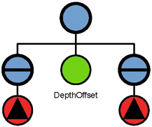
Each of these classes affects different elements of the rendering state, as described later in this section. Figure 5.16, “ Property-Node Classes ” shows the portion of the class tree for property nodes.
An SoMaterial( C++ | Java | .NET )node includes the following fields:
reflected color of an object in response to the ambient lighting in the scene. The default value for this field is [0.2, 0.2, 0.2]. | |
an object's base color. The default value for this field is [0.8, 0.8, 0.8]. | |
reflective quality of an object's highlights. The default value for this field is [0.0, 0.0, 0.0]. | |
light produced by an object. The default value for this field is [0.0, 0.0, 0.0]. | |
degree of shininess of an object's surface, ranging from 0.0 for a diffuse surface with no shininess to a maximum of 1.0 for a highly polished surface. The default value for this field is 0.2. | |
degree of transparency of an object's surface, ranging from 0.0 for an opaque surface to 1.0 for a completely transparent surface. The default value for this field is 0.0. |
![[Tip]](../images/tip.jpg) | |
Tip: The transparency type is specified in the render action (see Chapter 8, Applying Actions). |
An example of setting values in an SoMaterial( C++ | Java | .NET ) node is the following:
C++
SoMaterial *gold	  = new SoMaterial;
//Set material values
gold->ambientColor.setValue(.3, .1, .1);
gold->diffuseColor.setValue(.8, .7, .2);
gold->specularColor.setValue(.4, .3, .1);
gold->shininess = .4;
.NET
SoMaterial gold	  = new SoMaterial();
//Set material values
gold.ambientColor.SetValue(.3f, .1f, .1f);
gold.diffuseColor.SetValue(.8f, .7f, .2f);
gold.specularColor.SetValue(.4f, .3f, .1f);
gold.shininess.SetValue(.4f);
Java
SoMaterial gold	  = new SoMaterial();
//Set material values
gold.ambientColor.setValue(.3f, .1f, .1f);
gold.diffuseColor.setValue(.8f, .7f, .2f);
gold.specularColor.setValue(.4f, .3f, .1f);
gold.shininess.setValue(.4f);
Since gold is opaque, you can use the default value of 0.0 for the transparency field.
SoBaseColor( C++ | Java | .NET ), another class derived from SoNode( C++ | Java | .NET ), replaces only the diffuse color field of the current material and has no effect on other material fields.
| |
Tip: If you are changing only the diffuse color of an object, use an SoBaseColor( C++ | Java | .NET ) node in place of an SoMaterial( C++ | Java | .NET ) node. For example, to represent a complex terrain that uses many different diffuse colors, use one SoMaterial( C++ | Java | .NET ) node for the ambient, specular, and emissive color values, and then use one SoBaseColor( C++ | Java | .NET ) node with multiple values for the changing diffuse colors. The SoBaseColor( C++ | Java | .NET ) class is also useful when the light model is BASE_COLOR (see the section called “Light-Model Node”). |
An SoDrawStyle( C++ | Java | .NET ) node includes the following fields:
current drawing style. Values for this field are | |
| SoDrawStyle::FILLED filled regions (default) SoDrawStyle::LINES nonfilled outlines SoDrawStyle::POINTS points SoDrawStyle::INVISIBLE not drawn at all |
(for POINTS style) radius of points, in printer's points. The default value is 0.0. A value of 0.0 indicates to use the fastest value for rendering, which is typically 1.0. If this value is not 0.0, the point size is scaled by the amount required to keep it a constant size, which depends on the pixels per inch of the viewport region. |
| |
Tip: Draw-style LINES and POINTS look best with a BASE_COLOR lighting model. |
Figure 5.17, “ Drawing Styles (FILLED, LINES, POINTS)” shows the same object rendered in different drawing styles.
An SoLightModel( C++ | Java | .NET ) node includes the following field:
![[Note]](../images/note.jpg)
Figure B.4, “ Plate 4 ” and Figure B.5, “ Plate 5 ” show the same scene with the different lighting models. (Figure B.4, “ Plate 4 ” uses BASE_COLOR, and Figure B.5, “ Plate 5 ” uses PHONG.)
SoMaterial( C++ | Java | .NET ) and SoBaseColor( C++ | Java | .NET ) can be used along with any drawing style and any lighting model. In some cases, however, some of the material attributes might be ignored. For example, if you specify BASE_COLOR for the SoLightModel model field, only the diffuse color and transparency of the current material are used. But what happens if you specify only a base color (with SoBaseColor( C++ | Java | .NET )) and subsequently select the Phong lighting model for SoLightModel( C++ | Java | .NET )? In this case, Inventor uses the base color for the diffuse color and the default or current material element values for the other SoMaterial( C++ | Java | .NET ) fields.
You can use the SoEnvironment( C++ | Java | .NET ) node to simulate various atmospheric effects such as fog, haze, pollution, and smoke. For general purposes, these atmospheric effects are grouped under the term fog. The difference between fog and haze, for example, is simply the color and density.
Specifically, the SoEnvironment( C++ | Java | .NET ) node allows you to specify the color and intensity of the ambient lighting, the light attenuation for point lights and spotlights, and the type, color, and visibility factor for fog. Figure B.6, “ Plate 6 ” shows the effects of an SoEnvironment( C++ | Java | .NET ) node. This image uses a value of FOG for the fog type. The fogColor is (0.2, 0.2, 0.46).
An SoEnvironment( C++ | Java | .NET )node includes the following fields:
| |
Tip: For realistic scenes, clear the window to the fog color before drawing the fogged objects (see the SoXtRenderArea( C++ )::setBackgroundColor() method.) |
By default, Inventor does not assume anything about how the vertices in a vertex shape are ordered, whether its surface is closed or open, or whether the faces of the shape are convex or concave. If you know that the vertices are in a consistent order, that the shape is closed, or that the shape faces are convex, you can use the SoShapeHints( C++ | Java | .NET ) node to notify Inventor so that it can optimize certain rendering features.
The SoShapeHints( C++ | Java | .NET ) node has four fields:
vertexOrdering (SoSFEnum) | provides hints about the ordering of the faces of a vertex-based shape derived from SoVertexShape( C++ | Java | .NET ). This field describes the ordering of all the vertices of all the faces of the shape when it is viewed from the outside. |
| Values for this field are |
| SoShapeHints::UNKNOWN_ORDERING the ordering of the vertices is not known (the default) SoShapeHints::CLOCKWISE the vertices for each face are specified in clockwise order SoShapeHints::COUNTERCLOCKWISE the vertices for each face are specified in counterclockwise order |
shapeType (SoSFEnum) | SoShapeHints::UNKNOWN_SHAPE_TYPE the shape type is not known (the default) SoShapeHints::SOLID the shape is a solid object (not an open surface) |
faceType (SoSFEnum) | SoShapeHints::UNKNOWN_FACE_TYPE the face type is not known SoShapeHints::CONVEX all faces of the shape are convex (the default) |
creaseAngle (SoSFFloat) | used for automatic normal generation. See the section called “Generating Normals Automatically” |
If the shapeType is SOLID and the vertexOrdering is either CLOCKWISE or COUNTERCLOCKWISE, Inventor turns on backface culling and turns off two-sided lighting. If the shapeType is not SOLID and the vertexOrdering is either CLOCKWISE or COUNTERCLOCKWISE, Inventor turns off backface culling and turns on two-sided lighting. In all other cases, backface culling and two-sided lighting are both off. If you use the SoShapeHints( C++ | Java | .NET ) node, be sure to describe the object accurately; otherwise, objects may be rendered incorrectly.
Use the SoComplexity( C++ | Java | .NET ) node to indicate the amount of subdivision into polygons for subsequent shape nodes in the scene graph. This node has three fields:
type (SoSFEnum) | general type of complexity. Values for this field are |
| SoComplexity::OBJECT_SPACE (the default) bases the subdivision on the object itself, regardless of where it is on the screen or which parts are closer to the viewer. SoComplexity::SCREEN_SPACE bases the complexity on the amount of screen space occupied by the object. Objects requiring the full screen require more detail; small objects require less detail. The result is that objects that are closer to the viewer usually receive more detail than objects that are farther away. This type of complexity is more expensive to compute than the others. In addition, it invalidates the render cache when the camera moves (see the discussion of render caching in Chapter 8, Applying Actions). SoComplexity::BOUNDING_BOX renders a bounding box in place of the shape. This type is used for speed, when exact shapes are not required. It uses the current drawing style to render the box. |
value (SoSFFloat) | a value that provides a hint about the amount of subdivision desired, where 0.0 is minimum complexity and 1.0 is maximum complexity. The default is 0.5. |
textureQuality (SoSFFloat) | a value that provides a hint about the quality of texture mapping used on the object. The trade-off is between speed of rendering and quality of texturing. A value of 0.0 indicates maximum speed (possibly turning off texturing completely), and 1.0 indicates finest texture quality. The default is 0.5. |
Figure 5.18, “ Specifying Different Levels of Complexity (left: OBJECT_SPACE; right: SCREEN_SPACE)” shows the same object with different levels of complexity. The spheres at the left use object-space complexity and a complexity value of .5. The spheres at the right use screen-space complexity and a complexity value of .06. The NURBS examples in Chapter 20, Curves and Surfaces use the SoComplexity( C++ | Java | .NET ) node.
Inventor lets you define your data in a variety of different units. It uses meters as its default units, but you can use the SoUnits( C++ | Java | .NET ) node to specify a different unit of measurement. The units node acts like a scale node by scaling subsequent shapes into the specified units. SoUnits( C++ | Java | .NET ) can adjust the amount it scales an object by checking to see if any other units have been defined. The units node adjusts the scale so that the previously defined units are no longer in effect.
The SoUnits( C++ | Java | .NET ) node has one field:
units (SoSFEnum) | defines the current unit of measurement to be applied to all subsequent shapes in the scene graph. Possible values are as follows: SoUnits::METERS SoUnits::CENTIMETERS SoUnits::MILLIMETERS SoUnits::MICROMETERS SoUnits::MICRONS SoUnits::NANOMETERS SoUnits::ANGSTROMS SoUnits::KILOMETERS SoUnits::FEET SoUnits::INCHES SoUnits::POINTS SoUnits::YARDS SoUnits::MILES SoUnits::NAUTICAL_MILES |
To render your data in units other than these, use an SoUnits( C++ | Java | .NET ) node to set the current units back to meters, followed by a scale node that scales from meters into the desired units.
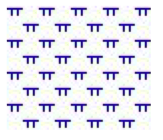
A pattern is a 32x32 bitmap that’s interpreted as a mask of 0s and 1s. Where a 1 appears, the corresponding pixel in the polygon is drawn; where a 0 appears, nothing is drawn. Using patterns is like using screen door transparency where you specify the pattern of the screen. OpenGL polygon stippling is used to render the pattern.
You can load a pattern file with method loadPatterns(). If the specified file name is not found, a default pattern will be used. If you specify only the file name without the path, the file will be loaded from the directory $OIVHOME/data/patterns/. If you want to specify your own path, give the path associated with the file name. (See method loadPatterns()).
You can load a pattern file containing one or more patterns using the loadPatterns() method or you can define and load patterns programmatically using the addPattern() method. It is possible to use this method before or without loadPatterns(). In this case, you must define a pattern buffer as shown below:
C++
static unsigned char pattBuffer[128] =
{
  0xFF,0x00,0xFF,0x00,
  0x30,0x00,0x30,0x00,
  0x18, ...
};
.NET
public static byte[] pattBuffer = new byte[128]
{
  0xFF,0x00,0xFF,0x00,
  0x30,0x00,0x30,0x00,
  0x18, ...
};
Java
public static byte[] pattBuffer = new byte[]
{
  (byte) 0xFF,(byte) 0x00,(byte) 0xFF,(byte) 0x00,
  (byte) 0x30,(byte) 0x00,(byte) 0x30,(byte) 0x00,
  (byte) 0x18, ...
};
This is an array of 128 bytes.
If you do not use either of these two methods, the default pattern will be used. Likewise, if you set the name or category fields with a bad name or category, the default pattern will be used.
Example 5.5. The file extension for a pattern file is “.pat”
"GEOLOGY"
# The first string is the category name of the first pattern.
# This is a comment !

"PATTERN N1"
# The second string is the name of the pattern.
# To define the pattern, you must define a 32x32 sequence of
# '1' and '0'.

  0 0 0 0 0 0 0 0 0 0 0 0 0 0 0 0 0 0 0 0 0 0 0 0 0 0 0 0 0 0 0 0
  0 0 0 0 0 0 0 0 0 0 0 0 0 0 0 0 0 0 0 0 0 0 0 0 0 0 0 0 0 0 0 0
  0 0 0 0 0 0 0 0 0 0 0 0 0 0 0 0 0 0 0 0 0 0 0 0 0 0 0 0 0 0 0 0
  0 0 0 0 0 0 0 0 1 1 1 1 1 1 1 1 ...
#============================================
"PATTERN N2"
  0 0 0 0 0 0 0 0 0 0 0 0 0 0 0 0 0 0 0 0 0 0 0 0 0 0 0 0 0 0 0 0
  0 0 0 0 0 0 0 0 0 0 0 0 0 0 0 0 0 0 0 0 0 0 0 0 0 0 0 0 0 0 0 0
  0 0 0 0 0 0 0 0 0 0 0 0 0 0 0 0 0 0 0 0 0 0 0 0 0 0 0 0 0 0 0 0
  0 0 0 0 0 0 0 0 1 1 1 1 1 1 1 1 ...
In this figure, you can see a pattern file that defines two patterns in the “GEOLOGY” category.
![[Warning]](../images/warning.jpg) | |
There can only be one category per file. |
Example 5.6. How to create a FaceSet filled with a pattern
C++
// We want to use all the patterns of the file except for the
// first one! In this case all patterns from the file "geology.pat"
// will be loaded, but not the "PATTERN N1" pattern.
// (If the FilterType had been "SoPattern::INCLUSIVE_FILTER",
// only "PATTERN N1" would have been loaded.)

  filterNames[0] = (SbString)"PATTERN N1";
  numFilters = 1;
  SoPattern::loadPatterns("geology.pat", numFilters, filterNames,
                           SoPattern::EXCLUSIVE_FILTER);

// Now that we have a list of patterns, we can use them
// on a face set.

// Here we define the color of the pattern.
  SoMaterial *myMaterial = new SoMaterial;
  root->addChild(myMaterial);
  myMaterial->diffuseColor.setValue(0., 0., 1.);

// Creation of the pattern.
  SoPattern *myPattern = new SoPattern;
  root->addChild(myPattern);
// Here we decide to use the pattern from the category "GEOLOGY"
// and the name "PATTERN N4".
  myPattern->category.setValue("GEOLOGY");
  myPattern->name.setValue("PATTERN N4");

// Creation of the Face Set.
  SoVertexProperty *myVertexProperty = new SoVertexProperty();
  myVertexProperty->vertex.setValues(0, 6, vertices);

  SoFaceSet *myFaceSet = new SoFaceSet;
  myFaceSet->vertexProperty.setValue((SoNode*)myVertexProperty);
  myFaceSet->numVertices.setValues(0, 2, numVertices);
  root->addChild(myFaceSet);
.NET
// We want to use all the patterns of the file except for the
// first one! In this case all patterns from the file "geology.pat"
// will be loaded, but not the "PATTERN N1" pattern.
// (If the FilterType had been "SoPattern::INCLUSIVE_FILTER",
// only "PATTERN N1" would have been loaded.)

filterNames[0] = "PATTERN N1";
numFilters = 1;
if(Environment.GetCommandLineArgs().Length > 1 )
  SoPattern.LoadPatterns(Environment.GetCommandLineArgs()[1],
     numFilters, filterNames, SoPattern.FilterTypes.EXCLUSIVE_FILTER);
else
{
  SoPattern.LoadPatterns(filepath, numFilters, filterNames,
     SoPattern.FilterTypes.EXCLUSIVE_FILTER);
}

// Now that we have a list of patterns, we can use them
// on a face set.

// Here we define the color of the pattern.
SoMaterial myLeftMaterial = new SoMaterial();
root.AddChild(myLeftMaterial);
myLeftMaterial.diffuseColor.SetValue(0f, 0f, 1f);

// Pattern.
SoPattern myLeftPattern = new SoPattern();
root.AddChild(myLeftPattern);
// Here we decide to use the pattern from the category "GEOLOGY"
myLeftPattern.category = "GEOLOGY";
myLeftPattern.name = "PATTERN N4";

SoVertexProperty myLeftVertexProperty = new SoVertexProperty();
myLeftVertexProperty.vertex.SetValues(0, 6, vertices);

SoFaceSet myLeftFaceSet = new SoFaceSet();
myLeftFaceSet.vertexProperty.Value = myLeftVertexProperty;
myLeftFaceSet.numVertices.SetValues(0, numVertices);
root.AddChild(myLeftFaceSet);
Java
// I want all the pattern of the file but not the first one !
String filterNames[] = {"PATTERN N1"};

if ( !SoPattern.loadPatterns(m_prefix + "../../../../data/textures/Pattern.pat", filterNames,
      SoPattern.FilterTypes.EXCLUSIVE_FILTER) )
System.err.println("Cannot load pattern file : Pattern.pat");

SoTransform myTransfo = new SoTransform();
myTransfo.translation.setValue( -1.F, 0.F, 0.F );

SoMaterial myLeftMaterial = new SoMaterial();
myLeftMaterial.diffuseColor.setValue( 0.F, 0.F, 1.F );

// Pattern.
SoPattern myLeftPattern = new SoPattern();
myLeftPattern.category.setValue("GEOLOGY");
myLeftPattern.name.setValue("PATTERN N4");

SoCoordinate3 myLeftCoord = new SoCoordinate3();
myLeftCoord.point.setValues( 0, vertices );

SoFaceSet myLeftFaceSet = new SoFaceSet();
myLeftFaceSet.numVertices.setValues( 0, numVertices );

SoSeparator leftSep = new SoSeparator();
{
  leftSep.addChild( myTransfo );
  leftSep.addChild( myLeftMaterial );
  leftSep.addChild( myLeftPattern );
  leftSep.addChild( myLeftCoord );
  leftSep.addChild( myLeftFaceSet );
}
It is often useful to draw multiple primitives on the same plane in 3D space. For example we might want to draw lines on top of a polygonal surface to show the edges of the faces that form the surface. We might also want to draw text or additional polygons on top of a polygon. In a perfect world co-planar geometry would be resolved by the default “less than or equal” depth test so that whatever is drawn last appears on top. Unfortunately this is not reliable in practice. Usually the result is the depth buffer artifacts commonly called “stitching”. Open Inventor provides two nodes that allow you to introduce a small depth offset in order to reliably separate co-planar geometry. They are SoPolygonOffset( C++ | Java | .NET ) and SoDepthOffset( C++ | Java | .NET ).
The SoPolygonOffset( C++ | Java | .NET ) property node provides a convenient implementation of the OpenGL polygon offset feature (glPolygonOffset), which is typically implemented in hardware.
The styles field is a bit-wise combination of FILLED, LINES, and POINTS, and determines which polygon draw style mode should be offset. For instance, if styles = LINES, only polygons whose drawstyle mode is wireframe (SoDrawStyle::LINES) are offset.
The two fields, factor and units, are used to calculate an offset added to the depth value of each fragment of polygons. The offset value is computed as follows:
offset = m *
factor
+ r *
units
where r is an OpenGL implementation-specific constant representing the smallest resolvable unit of distance in the depth buffer and m is the maximum depth slope of the polygon. For polygons that are parallel to the near and far camera clipping planes (perpendicular to the view vector), the depth slope is zero. So for polygons in your scene graph with a depth slope near zero, a small value for units is usually sufficient to separate co-planar geometry. But for polygons that are angled away from the view vector, a larger offset is usually needed (see the diagrams in the SoDepthOffset( C++ | Java | .NET ) section). Because the depth slope increases with the angle of the polygon, you can use the factor field to add an additional offset that increases with the angle of the polygon. Because the angle of the polygon can change constantly as the camera and/or scene rotate, you should start by setting both units and factor to a small value, e.g. 1. Larger values may be required in some cases.
If the offset is positive, polygons are pushed away from the camera (drawn closer to the far plane). If the offset is negative, polygons are pulled toward the camera (drawn closer to the near plane). Therefore if we wanted to draw lines on top of a polygon, we could use an SoLineSet( C++ | Java | .NET ) for the lines (which is not affected by SoPolygonOffset( C++ | Java | .NET )) and put an SoPolygonOffset( C++ | Java | .NET ) node with units and factor set to 1 before the polygon, as shown in the following example program.
Note that SoPolygonOffset( C++ | Java | .NET ) only affects polygonal geometry. It does not affect lines, text or other types of geometry. When an SoPolygonOffset( C++ | Java | .NET ) node is traversed, the values of its fields replace the current values in the traversal state. The polygon offset values are pushed and popped by SoSeparator( C++ | Java | .NET ) like other properties.
Example 5.7. How to use SoPolygonOffset
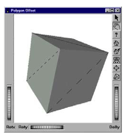 Without polygon offset |
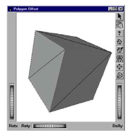 With polygon offset |
This example shows a cube with a diagonal line on each face of the cube. The program source code can be found in:$OIVHOME/src/Inventor/examples/Features/PolygonOffset/polygonOffset.cxx.
On the left, you can see the artifacts (“stitching”) that appear when the SoPolygonOffset( C++ | Java | .NET )node is not used.
C++
int
main(int argc, char **argv)
{
static SbVec3f vertices[12] =
  {
  SbVec3f(1, 1, 1),    SbVec3f(-1, -1, 1),  SbVec3f(1, 1, 1),
  SbVec3f(-1, 1, -1),  SbVec3f(1, 1, 1),    SbVec3f(1, -1, -1),
  SbVec3f(-1, -1, -1), SbVec3f(1, 1, -1),   SbVec3f(-1, -1, -1),
  SbVec3f(1, -1, 1),   SbVec3f(-1, -1, -1), SbVec3f(-1, 1, 1)
  };

// Initialize Inventor and Xt
Widget myWindow = SoXt::init(argv[0]);

  SoSeparator *root = new SoSeparator;
  SoSeparator *sep = new SoSeparator;
  SoCube *cube = new SoCube;
  SoCoordinate3 *coords = new SoCoordinate3;
  coords->point.setValues(0, 12, (const class SbVec3f *)vertices);

  SoLineSet *lineSet = new SoLineSet;
  lineSet->numVertices.set1Value(0, 12);

  SoPolygonOffset *polygonOffset = new SoPolygonOffset;
  polygonOffset->factor = 1.;
  polygonOffset->units = 1.;

  SoMaterial *mat = new SoMaterial;
  mat->diffuseColor.setValue(1, 0, 0);

  SoSeparator *cubeSep = new SoSeparator;
  cubeSep->addChild(cube);
  cubeSep->addChild(mat);
  cubeSep->addChild(coords);
  cubeSep->addChild(lineSet);

  root->ref();
  root->addChild(sep);

  sep->addChild(polygonOffset);
  sep->addChild(cubeSep);

// Create a viewer
  SoXtExaminerViewer *myViewer = new SoXtExaminerViewer(myWindow);

// attach and show viewer
  myViewer->setSceneGraph(root);
  myViewer->setTitle("Polygon Offset");
  myViewer->show();

// Loop forever
  SoXt::show(myWindow);
  SoXt::mainLoop();
  return 0;
}
.NET
SbVec3f[] vertices = new SbVec3f[12]
{
  new SbVec3f(1, 1, 1),    new SbVec3f(-1, -1, 1),
  new SbVec3f(1, 1, 1),    new SbVec3f(-1, 1, -1),
  new SbVec3f(1, 1, 1),    new SbVec3f(1, -1, -1),
  new SbVec3f(-1, -1, -1), new SbVec3f(1, 1, -1),
  new SbVec3f(-1, -1, -1), new SbVec3f(1, -1, 1),
  new SbVec3f(-1, -1, -1), new SbVec3f(-1, 1, 1)
};

// Initialize Inventor

SoSeparator root = new SoSeparator();
SoSeparator sep = new SoSeparator();
SoCube cube = new SoCube();

SoCoordinate3 coords = new SoCoordinate3();
coords.point.SetValues(0, vertices);

SoLineSet lineSet = new SoLineSet();
lineSet.numVertices[0] = 12;

SoPolygonOffset polygonOffset =  new SoPolygonOffset();
polygonOffset.factor.Value = 1f;
polygonOffset.units.Value = 1f;

SoMaterial mat = new SoMaterial();
mat.diffuseColor.SetValue(1, 0, 0);

SoSeparator cubeSep = new SoSeparator();
cubeSep.AddChild(cube);
cubeSep.AddChild(mat);
cubeSep.AddChild(coords);
cubeSep.AddChild(lineSet);

root.AddChild(sep);

sep.AddChild(polygonOffset);
sep.AddChild(cubeSep);

// Create a viewer
SoWinExaminerViewer myViewer = new SoWinExaminerViewer(this, "", true,
	    SoWinFullViewer.BuildFlags.BUILD_ALL, SoWinViewer.Types.BROWSER);

// attach and show viewer
myViewer.SetSceneGraph(root);
myViewer.SetTitle("Polygon Offset");
myViewer.Show();
Java
SbVec3f[] vertices = new SbVec3f[]
{
  new SbVec3f(1, 1, 1),    new SbVec3f(-1, -1, 1),  new SbVec3f(1, 1, 1),
  new SbVec3f(-1, 1, -1),  new SbVec3f(1, 1, 1),    new SbVec3f(1, -1, -1),
  new SbVec3f(-1, -1, -1), new SbVec3f(1, 1, -1),   new SbVec3f(-1, -1, -1),
  new SbVec3f(1, -1, 1),   new SbVec3f(-1, -1, -1), new SbVec3f(-1, 1, 1)
};

// Initialize Inventor and Xt

SoSeparator root = new SoSeparator();
SoSeparator sep = new SoSeparator();
SoCube cube = new SoCube();

SoCoordinate3 coords = new SoCoordinate3();
coords.point.setValues(0, vertices);

SoLineSet lineSet = new SoLineSet();
lineSet.numVertices.set1Value(0, 12);

SoPolygonOffset polygonOffset = new SoPolygonOffset();
polygonOffset.factor.setValue(1f);
polygonOffset.units.setValue(1f);

SoMaterial mat = new SoMaterial();
mat.diffuseColor.setValue(1, 0, 0);

SoSeparator cubeSep = new SoSeparator();
cubeSep.addChild(cube);
cubeSep.addChild(mat);
cubeSep.addChild(coords);
cubeSep.addChild(lineSet);

root.addChild(sep);

sep.addChild(polygonOffset);
sep.addChild(cubeSep);

// Create a viewer
myViewer = new SwSimpleViewer(SwSimpleViewer.EXAMINER);
// attach and show viewer
myViewer.setSceneGraph(root);

myViewer = new SwSimpleViewer();
myViewer.setSceneGraph(root);
myViewer.setName("Polygon offset");
myViewer.viewAll();

panel.add(myViewer);
add(panel);
The SoDepthOffset( C++ | Java | .NET ) node can also be used to resolve depth buffer artifacts (“stitching”) for co-planar geometry. This node uses a different algorithm (based on Lengyel’s method from Game Programming Gems) in which the projection matrix is modified to offset subsequent geometry. As a result it has advantages over SoPolygonOffset( C++ | Java | .NET ) in some cases. Specifically, SoDepthOffset( C++ | Java | .NET ) applies its offset value to all types of geometry, not just polygons, and also does not require any additional per-vertex calculations on the GPU.
Note! The most important difference between SoPolygonOffset( C++ | Java | .NET ) and SoDepthOffset( C++ | Java | .NET ) is the direction of the offset. For SoPolygonOffset( C++ | Java | .NET ) a positive value moves the geometry away from the camera (farther in depth). For SoDepthOffset( C++ | Java | .NET ) a positive value moves the geometry toward the camera (closer in depth).
SoDepthOffset( C++ | Java | .NET ) has two other differences. First, since SoDepthOffset( C++ | Java | .NET ) requires the projection matrix to be modified during traversal, it may prevent building a render cache for part of the scene graph. Second, the offset does not take into account the depth slope of the geometry, so a larger offset may be required for geometry that is not perpendicular to the view vector.
The render caching issue is easily handled, by adjusting your scene graph structure, just as you would for any non-cacheable node, to ensure that the actual shape nodes are cached even if the parent group node cannot cache:
|
|
|
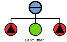
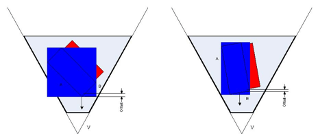
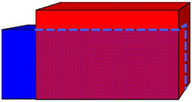
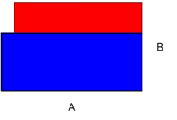
Consider two shapes A and B that have a co-planar (front) face.
 Front view |
 Top view |
Defining a positive offset for the blue shape will cause it to be moved toward the camera. The visual artifact for coplanar faces is removed.
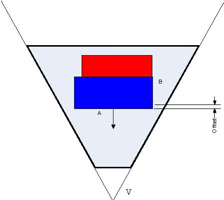
An important point to keep in mind when using the SoDepthOffset( C++ | Java | .NET ) node is that only a simple depth modification is done. The depth slope of the geometry is not considered. As a consequence, the full offset is realized when a polygon face is perpendicular to the view vector, but while rotating the scene, the offset effectively becomes smaller as the face becomes closer to parallel to the view vector.