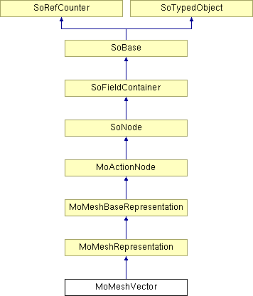
MoMeshVector Class Reference
[Representations]
 Rendering node that displays a vector data set.
More...
#include <MeshVizXLM/mapping/nodes/MoMeshVector.h>

Public Member Functions | |
| virtual SoType | getTypeId () const |
| MoMeshVector () | |
Static Public Member Functions | |
| static SoType | getClassTypeId () |
Public Attributes | |
| SoSFInt32 | vectorSetId |
| SoSFFloat | scaleFactor |
| SoSFFloat | shiftFactor |
| SoSFFloat | thicknessFactor |
| SoSFBool | arrow |
Detailed Description
 Rendering node that displays a vector data set.
Each value of the vector data set is represented by a line plus an optional small arrow or a cylinder and an optional cone depending of the thicknessFactor. The vectors are located at the cell centers for per cell data sets or at the node positions for per node data sets. The vectorSetId field defines the index of the vector set to display. This is an index into the list of vector sets existing in the traversal state (see the MoVec3Setxxx nodes).
The vectors can be colored using a scalar set defined in the colorScalarSetId inherited field. This is an index into the list of scalar sets existing in the traversal state (see the MoScalarSetxxx nodes). To disable coloring set this field to -1.
FILE FORMAT/DEFAULT
- MeshVector {
- See related examples:
-
Turbine, CellShape, ClipLine, FenceSlice, GridPlaneSlice, InterpolatedLogicalSlice, Isoline, LogicalSlice, Outline, Streamlines, Vectors
- < 0, nothing is rendered.
- = 0, each vector is displayed as a line (plus arrow if arrow is true).
- > 0, each vector is displayed as a cylinder (plus cone if arrow is true).
- MeshVizXLM/mapping/nodes/MoMeshVector.h
| colorScalarSetId | 0 |
| vectorSetId | 0 |
| scaleFactor | 1.0 |
| shiftFactor | 0.0 |
| thicknessFactor | 0.0 |
| arrow | true |
Constructor & Destructor Documentation
| MoMeshVector::MoMeshVector | ( | ) |
Constructor.
Member Function Documentation
| static SoType MoMeshVector::getClassTypeId | ( | ) | [static] |
Returns the type identifier for this class.
Reimplemented from MoMeshRepresentation.
| virtual SoType MoMeshVector::getTypeId | ( | ) | const [virtual] |
Returns the type identifier for this specific instance.
Reimplemented from MoMeshRepresentation.
Member Data Documentation
Draw arrows on vectors.
Default is true.
The scale factor to apply to the vector field to resize the representation.
Default is 1.0. All values are accepted. If scaleFactor is 0, the representation is empty.
The shift factor to apply to the representation of each vector.
Each vector is translated along its direction by the value of shiftFactor.
Default is 0.0 (no shift). All values are accepted.
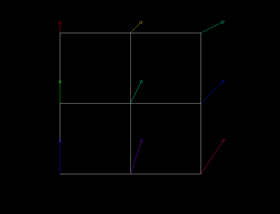
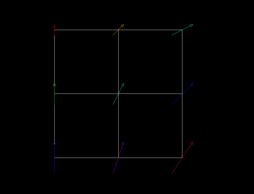
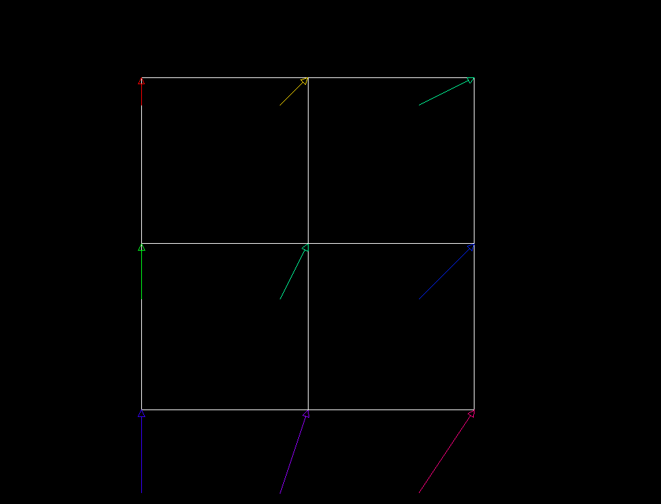
The following images illustrate the effect of shiftFactor on the vector field representation, with a vector set using a PER_NODE binding.

shiftFactor = 0.0

shiftFactor = -0.5

shiftFactor = -1.0
The thickness factor to apply to the representation of each vector.
If the thickness factor is:
Factor values > 0 control both the radius of the cylinder and the radius of the cone. For example, when the factor is 1 the radius of the cylinder is 5% of the average vector length in the data set. Larger factors also proportionally increase the height of the cone up to a maximum of half the vector length. When this limit is reached, larger values of the factor have no effect unless the arrow is removed by setting arrow to false.
Default is 0.0.
NOTE: field available since Open Inventor 10.1Specifies the vector set to display.
During traversal of the scene graph, vector sets are accumulated in a list of vector sets. vectorSetId is an index in this list. Default is 0 meaning the first set in the list.
The documentation for this class was generated from the following file: