Class SoFenceSlice
- All Implemented Interfaces:
SafeDisposable
axis field to form (in effect) an oblique slice. The default axis is Z, so the 2D points are treated as (X,Y) values. The points may be outside the 3D extent of the volume, but only the portion of the slice inside the volume will be drawn (subject to region of interest and other clipping nodes).
The SoVolumeData node on which this shape is applied can be specified with dataSetId. When this field is set to 0, the last SoVolumeData node on state is used.
A similar effect could be obtained using volume geometry (e.g. SoVolumeFaceSet), but SoFenceSlice is more convenient and is optimized for this specific case.
The 2D coordinates are interpreted according to the following table. See the code example below.
| Fence axis | Coordinate axes |
| X | Y , Z |
| Y | Z , X |
| Z | X , Y |
SoDataRange and SoTransferFunction. The current diffuse color and transparency (set, for example, with an SoMaterial node) modify the appearance of the slice. This means that, for example, the current transparency can be used as a
global alpha value to modulate the overall opacity of the slice. For an RGBA volume each voxel's RGBA value comes directly from the volume data.
The interpolation field controls how the texture is interpolated.
The alphaUse field (SoSlice) controls how the voxel's alpha component is used when drawing the fence slice.
Optionally a bump mapping effect may be applied. Normal vectors are automatically computed from the data value gradient. The enableBumpMapping and bumpScale fields (SoSlice) control whether bump mapping is active and the intensity of the effect.
Notes:
- Transformation matrices:
The volume size and orientation (like geometry) can be modified by transformation nodes in the scene graph and this in turn modifies the appearance of volume visualization nodes. However the same transformation must be applied to the volume data node and all volume visualization nodes associated with that volume. So effectively any transformation nodes that affect the volume must be placed before the volume data node. - Picking:
The entire slice is pickable, even where it is transparent as a result of the current transfer function. CurrentlySoFenceSlicedoes not provide anSoDetailobject. - Interpolation:
Interpolation is specified using theinterpolationfield. The default (LINEAR) does bi-linear interpolation between voxel values. The NEAREST value can be used to display individual voxels. For best image quality we recommend using the MULTISAMPLE_12 value. - Data range:
By default VolumeViz maps the entire range of the voxel's data type (e.g. 0..65535 for unsigned short) into the colormap. This is often correct for byte (8 bit) voxels, but seldom correct for 16 bit voxels and never correct for floating point voxels. Use anSoDataRangenode to specify the actual (or desired) range of data values to be mapped. Also use anSoDataRangenode to implement brightness/contrast control like the Window/Level setting commonly used with medical images. - Clipping:
Volume primitives can be clipped using a region of interest (SoROI), geometry (SoVolumeClippingGroup) and/or height fields (SoUniformGridClipping). They are also clipped by OpenGL clipping planes (SoClipPlane), but we recommend using the VolumeViz clipping nodes instead. - Material:
The color of each voxel is modulated by the current diffuse color in the traversal state. The default diffuse color is 0.8,0.8,0.8. This results in full intensity values in the color map being displayed as 80% intensity. Therefore we recommend adding anSoMaterialnode before the slice and setting its diffuseColor field to full white (1,1,1). - Transparency:
- Typically the color map (
SoTransferFunction) used for volume rendering (SoVolumeRender) assigns transparency (alpha < 1) to some voxel values. If you want to use the same color map for slice rendering, but render the slice completely opaque, set thealphaUsefield to ALPHA_OPAQUE. This overrides the alpha values in the color map (or an RGBA volume). However it does not affect transparency assigned using anSoMaterialnode.
- If you want to adjust the overall transparency of the slice, add an
SoMaterialnode and set its transparency field (keeping alphaUse set to ALPHA_AS_IS). Effectively a scale factor 1-transparency is applied to each voxel's alpha value.
- Intersecting transparent slices cannot be rendered correctly by the basic blending transparency algorithms. To render this case correctly, set the transparency algorithm to SORTED_PIXEL using the viewer class or
SoGLRenderAction.
- Typically the color map (
- Voxel edges:
The edges of the voxels can also be rendered. See options in theSoVolumeRenderingQualitynode. - Custom shaders:
The currentSoVolumeShadernode, if any, allows custom shaders to be defined for special computation or rendering effects, including blending multiple volumes. - Composition with Multiple Data:
It is possible to compose datasets that have different dimensions, tile sizes and transformations.
In order to help fetch the correct data values in custom shaders, texture coordinates conversion functions are provided in the VolumeViz/vvizStructure.h shader include.
For instance,
can be used to convert texture coordinates related to one dataset to texture coordinates related to another dataset.vec3 VVizTextureToTextureVec(in VVizDataSetId datasetSrc, in VVizDataSetId datasetDst, in vec3 texCoord);
The conversion is based solely on the transformations applied to each dataset, which are defined by their model matrix and their extent.
Please note that the model matrix of a dataset is defined by to theSoTransformationnodes that are placed before theSoDataSetnode in the order of the traversal. - Performance:
- Tile size:
For backward compatibility, the default tile size is still only 64. This is quite small for modern CPU/GPU hardware. The smaller the tile size, the larger the total number of tiles that must be managed by VolumeViz. This overhead can be significant, especially for operations that require reloading the data textures on the GPU, for example, changing the data range (SoDataRange). For smaller volumes, like 512^3, it can be efficient to set the tile size large enough to contain the entire volume. For very large volumes, larger tile sizes are efficient forSoVolumeRenderbut somewhat inefficient for slice rendering because complete tiles must be loaded even though the slice only uses part of the data. Applications should experiment.
For volumes stored in LDM file format, the tile size must be specified when the volume is converted to LDM (seeSoConverterand the "-t" option). For other data data formats the tile size can be specified using theSoVolumeDatanode's ldmResourceParameters field, but only after setting the filename field or calling the setReader() method. - Tile cache policy: It specifies how the tiles are stored in CPU memory. The selected policy can significantly impact the data loading performance versus the CPU memory footprint. See
SoLDMResourceParameters.tileCachePolicyfor detail.
- Tile size:
- Hardware requirements:
This node needs a graphic card with support for GLSL shader, vertex buffer objects (VBO) and framebuffer object (FBO). Use theisSupported()method to check if the current graphics board can render a FenceSlice.
Please see SoObliqueSlice for a complete code example. The following shows how to set up the axis and points fields of SoFenceSlice.
 SoFenceSlice fenceSlice = new SoFenceSlice();
   fenceSlice.axis.setValue( SoFenceSlice.AxisType.Y );
   fenceSlice.points.set1Value( 0, new SbVec2f(-0.2f, -0.66f) );
   fenceSlice.points.set1Value( 1, new SbVec2f( 0.2f, -0.4f ) );
   fenceSlice.points.set1Value( 2, new SbVec2f(-0.2f,  0.4f ) );
   fenceSlice.points.set1Value( 3, new SbVec2f( 0.2f,  0.66f) );
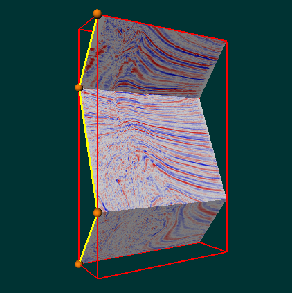
| Fence slice on Y axis (Colt example data set): |
 |
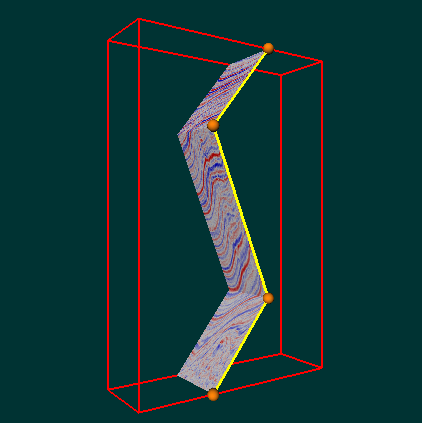
| Fence slice on X axis (Colt example data set): |
 |
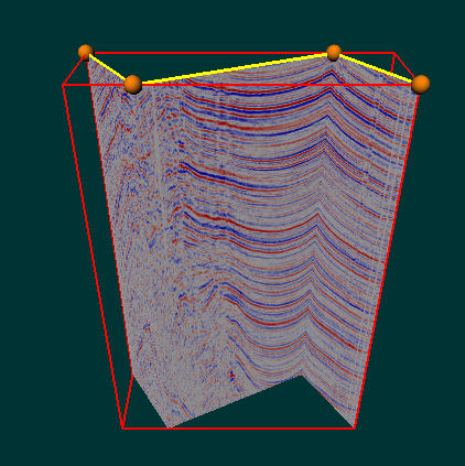
| Fence slice on Z axis (Colt example data set): |
 |
FenceSlice {
| dataSetId | 0 |
| points | [ ] |
| axis | Z |
| interpolation | LINEAR |
| alphaUse | ALPHA_BINARY |
| useRGBA | false |
| alternateRep | NULL |
| enableBumpMapping | false |
| bumpScale | 1.0 |
Action behavior:
SoGLRenderAction
Draws a textured shape based on current SoVolumeData, SoTransferFunction, and SoROI nodes.
SoGetBoundingBoxAction
Computes the bounding box that encloses the fence slice.
- See Also:
-
Nested Class Summary
Nested ClassesNested classes/interfaces inherited from class com.openinventor.volumeviz.nodes.SoSlice
SoSlice.AlphaUsesNested classes/interfaces inherited from class com.openinventor.volumeviz.nodes.SoVolumeShape
SoVolumeShape.Compositions, SoVolumeShape.InterpolationsNested classes/interfaces inherited from class com.openinventor.inventor.nodes.SoShape
SoShape.ShapeTypesNested classes/interfaces inherited from class com.openinventor.inventor.nodes.SoNode
SoNode.RenderModesNested classes/interfaces inherited from class com.openinventor.inventor.Inventor
Inventor.ConstructorCommand -
Field Summary
FieldsModifier and TypeFieldDescriptionfinal SoSFEnum<SoFenceSlice.AxisType> Extrusion axis: X, Y, or Z.final SoSFInt32Specifies theSoVolumeDatanode to use.final SoMFVec2fSet of points defining a lineset.Fields inherited from class com.openinventor.volumeviz.nodes.SoSlice
alphaUse, alternateRep, bumpScale, enableBumpMapping, largeSliceSupport, useRGBAFields inherited from class com.openinventor.volumeviz.nodes.SoVolumeShape
composition, interpolationFields inherited from class com.openinventor.inventor.nodes.SoShape
boundingBoxIgnoringFields inherited from class com.openinventor.inventor.Inventor
VERBOSE_LEVEL, ZeroHandle -
Constructor Summary
Constructors -
Method Summary
Modifier and TypeMethodDescriptionstatic booleanCalls isSupported((com.openinventor.inventor.misc.SoState)null).static booleanisSupported(SoState state) Returns true if graphic card can render anSoFenceSlice.Methods inherited from class com.openinventor.volumeviz.nodes.SoVolumeShape
setRenderProgressMethods inherited from class com.openinventor.inventor.nodes.SoShape
getShapeType, isPrimitiveRestartAvailable, isPrimitiveRestartAvailableMethods inherited from class com.openinventor.inventor.nodes.SoNode
affectsState, callback, copy, copy, distribute, doAction, getAlternateRep, getBoundingBox, getByName, getMatrix, getPrimitiveCount, getRenderEngineMode, getRenderUnitID, GLRender, GLRenderBelowPath, GLRenderInPath, GLRenderOffPath, grabEventsCleanup, grabEventsSetup, handleEvent, isBoundingBoxIgnoring, isOverride, pick, rayPick, search, setOverride, touch, writeMethods inherited from class com.openinventor.inventor.fields.SoFieldContainer
copyFieldValues, copyFieldValues, enableNotify, fieldsAreEqual, get, getAllFields, getEventIn, getEventOut, getField, getFieldName, hasDefaultValues, isNotifyEnabled, set, setToDefaultsMethods inherited from class com.openinventor.inventor.misc.SoBase
dispose, getName, isDisposable, isSynchronizable, setName, setSynchronizableMethods inherited from class com.openinventor.inventor.Inventor
getNativeResourceHandle
-
Field Details
-
dataSetId
Specifies theSoVolumeDatanode to use. This is useful when datasets of different dimensions are present in the scene graph. Please seeSoMultiDataSeparatorfor more details.When set to 0, the last
SoVolumeDatanode on state is used. Default is 0.- Since:
- Open Inventor 10.11.0
-
points
Set of points defining a lineset.
Ifaxisis:- X: points are Y,Z coordinates
- Y: points are Z,X coordinates
- Z: points are X,Y coordinates
All points should be inside the 3D extent of the volume.
-
axis
Extrusion axis: X, Y, or Z. . Default is Z.
-
-
Constructor Details
-
SoFenceSlice
public SoFenceSlice()Constructor.
-
-
Method Details
-
isSupported
public static boolean isSupported()Calls isSupported((com.openinventor.inventor.misc.SoState)null). -
isSupported
Returns true if graphic card can render anSoFenceSlice. GPU must support GLSL. When using a debug build of Open Inventor, some "no context available" warning messages may be generated. You can ignore them or seeSoGLExtensionfor an example of usingSoGLContextto avoid them.
-