Class SoVolumeRender
- All Implemented Interfaces:
SafeDisposable
numSlices and numSlicesControl fields. At each sample point a value is interpolated from the closest voxels. The interpolation technique is controlled by the interpolation field. Classification means that color and opacity are computed based on the current SoDataRange and SoTransferFunction (and possibly values from other volumes - see SoVolumeShader). Optional rendering effects may modify the base color and/or opacity. These effects are controlled by an SoVolumeRenderingQuality node and include lighting, shadows, edge coloring, boundary opacity and more. The sample is then composited with other samples along the ray. Composition is controlled by the renderMode field. By default colors are combined based on the opacity of the sample (alpha blending). The ray is terminated if it reaches full opacity or reaches the current depth in the depth buffer.
The voxel's color to be combined during the composition step are retrieved in 2 different ways according the type of volume data:
- For a volume containing scalar data values: each voxel's color is determined by applying the current
SoDataRangeandSoTransferFunctionto the voxel's value. - For an RGBA volume, each voxel's color comes directly from the volume data and the
SoDataRangeandSoTransferFunctionare ignored.
The voxel's color is also combined with the current base color and transparency (see definition of base color here) set for example with an SoMaterial or an SoPhysicalMaterial node. This means that, for example, the current transparency can be used as a *global alpha* scale factor to decrease the opacity of all voxels.
If the light SoLightModel.model is either PER_VERTEX_PHONG or PER_PIXEL_PHONG, the final voxel's color is also affected by the fields emissiveColor, specularColor and shininess of the current SoMaterial. If the light SoLightModel.model is PHYSICALLY_BASED the final voxel's color is also affected by the fields specular roughness metallic of the current SoPhysicalMaterial.
The samplingAlignment field controls whether the samples are axis aligned (perpendicular to one axis of the volume), view aligned (perpendicular to the view direction) or boundary aligned (each ray starts at the first intersected voxel with alpha value > 0). Generally boundary aligned slices should be used (better image quality). Using SoVolumeGroup, SoVolumeIsoSurface or SoProjection nodes will automatically switch to view-aligned samples.
The property nodes SoVolumeIsoSurface and SoVolumeDataDrawStyle add additional rendering styles and can be used, for example, to force SoVolumeRender to draw a GPU computed isosurface instead of volume rendering.
Example rendering:
# Multiple volumes:
VolumeViz provides several mechanisms for combining or rendering multiple volumes, depending on the application's specific requirements. There are several cases:
- CPU data combining The data values from multiple volumes can be combined on the CPU during data loading, using the
SoDataCompositornode. For example computing the "difference" between two volumes on the fly.SoLDMDataTransformandSoVolumeTransformcan be used to modify data for a single volume, for example scaling data values or computing a derived data set.SoLDMDataTransformis applied when data is loaded andSoVolumeTransformis applied before data is transferred to the GPU. - Multiple data sets These are volumes that are really multiple data sets on the same "grid", in other words volumes having exactly the same dimensions and extent. For example, seismic attribute volumes. These volumes can be combined on the GPU using a simple fragment shader function. For example, replacing the VVizComputeFragmentColor (GLSL) function allows "co-blending" the colors from multiple volumes. See
SoVolumeShaderfor more details. Use anSoMultiDataSeparatornode to group the volume data nodes that should be combined. Multiple independent volumes These are volumes in the same scene that are completely independent (but might overlap in space) or have different dimensions or different extents. For example, medical datasets from different modalities. In order to ensure that the rendering of overlapping transparent volumes is properly interleaved, there are 2 options:
- if each volume needs their own rendering parameters and shading options, then use an
SoVolumeGroupnode to group the volume data nodes and rendering nodes, with anSoVolumeRendernode for each volume. - if the same rendering parameters and shading options can be applied to all volumes, then use an
SoMultiDataSeparatornode to group the volume data nodes and a singleSoVolumeRendernode. This option should be preferred as it does not suffer the limitations ofSoVolumeGroup. However, note thatSoVolumeRenderingQuality.voxelizedRenderingis not supported by this feature.
- if each volume needs their own rendering parameters and shading options, then use an
# Custom shaders:
The SoVolumeShader node allows a variety of custom shader functions to be defined for special computation or rendering effects on single volumes or multiple volumes. All of these features require programmable shader support on the GPU. Be sure to use an SoMultiDataSeparator (instead of SoSeparator) when combining multiple volumes.
# Composition of multiple independent volumes:
It is possible to compose datasets that have different dimensions, tile sizes and transformations. In those cases, the volume rendering will be applied on the union of the extents of all the SoVolumeData nodes on state.
In addition, texture coordinates conversion functions are provided in the VolumeViz/vvizStructure.h* shader include in order to help fetch the correct data values in custom shaders.
For instance,
can be used to convert texture coordinates related to one dataset to texture coordinates related to another dataset.vec3 VVizTextureToTextureVec(in VVizDataSetId datasetSrc, in VVizDataSetId datasetDst, in vec3 texCoord);
The conversion is based solely on the transformations applied to each dataset, which are defined by their model matrix and their extent. Please note that the model matrix of a dataset is defined by to the SoTransformation nodes that are placed **before** the SoDataSet node in the order of the traversal.
See SoVolumeShader.FRAGMENT_COMPUTE_COLOR for an example of a shader implementing the VVizComputeFragmentColor() function in that case.
# Lighting
The SoVolumeRenderingQuality property node allows you to to enable GPU computed lighting based on the first SoLight node in the scene graph. (Note that this is typically the viewer's "headlight".) VolumeViz supports two lighting algorithms. They are both computed on the GPU and are independent (but normally only one should be enabled).
- Gradient lighting Computes the effect of lighting for every sample along the ray, similar to the computation for polygonal geometry, but using a gradient vector computed from the voxel data values instead of a normal vector. Gradient lighting is enabled by the field
SoVolumeRenderingQuality.lighting. Gradient lighting is the classic solution but can have problems in relatively homogeneous regions where the gradient magnitude is small and gradient direction somewhat random. Multiple fields affect this computation including interpolation, gradientThreshold, gradientQuality and surfaceScalarExponent. - Deferred lighting Computes the effect of lighting for every visible voxel, as a post-processing step, using a gradient vector computed from the (visible) voxel depth values. Deferred lighting is enabled by the field
SoVolumeRenderingQuality.deferredLighting. Deferred lighting generally provides better performance because fewer lighting computations are needed. Deferred lighting generally provides better image quality for volumes that inherently contain surfaces (sharp gradients) like medical and industrial scans. Deferred lighting is most effective when the opacity values in the transfer function are approximately binary (mostly 0 and 1 values). See also theopacityThresholdfield.
# Shadows:
Open Inventor shadow rendering works for volume rendering similar to any other geometry. When shadow rendering is enabled (see SoShadowGroup), non-transparent voxels can cast and receive shadows (see SoShadowStyle). Shadow rendering is independent of whether lighting is enabled for the volume.
SoVolumeRender also supports "ambient occlusion" rendering (see the field SoVolumeRenderingQuality.ambientOcclusion). This rendering mode is visually a kind of self-shadowing and represents an approximation of the effect of ambient global lighting in the scene. Ambient occlusion can be combined with gradient or deferred lighting and with shadow casting.
# Clipping:
VolumeViz provides multiple tools for clipping volume rendering. Any or all of these tools may be combined for more complex clipping situations. Note that these tools clip all volume shapes including slices.
- The
SoROI(Region of Interest) node limits volume rendering to a subvolume. TheSoROInode's EXCLUSION_BOX mode can also be used to exclude a sub-region, forming what is sometimes called a "chair cut". Note that the Region of Interest also limits *data loading *, so it is valuable when the total size of the volume exceeds the available system memory. - The
SoVolumeClippingGroupnode clips volume rendering to any closed shape defined by a group of standard Open Inventor geometry nodes. Both "inside" and "outside" clipping are supported. TheSoScreenDrawer,SbExtrusionGeneratorandSoCSGShapenodes are useful for creating clipping geometry for interactive volume "sculpting". - The
SoUniformGridClippingandSoUniformGridProjectionClippingnodes clip volume rendering against one or more surfaces defined by a height field. This is particularly useful in seismic applications for clipping against (or between) horizon surfaces. - The
SoVolumeMasknode can be used to clip volume rendering against a boolean mask volume on a per-voxel basis. But the mask mechanism is much more powerful than that. Each region can have its own transfer function (color map) usingSoTransferFunctionnodes. Each region can also have its own draw style (volume rendering, isosurface or boundary) usingSoVolumeDataDrawStylenodes. Each region, including the original unmasked volume, is only visible if there exists a transfer function (SoTransferFunction) with the same id value.
# Picking:
SoRayPickAction handles picking of VolumeViz shapes similar to other geometry in the scene, but with additional features. Picking on an SoVolumeRender node can return the first non-transparent voxel "hit" or the entire set of intersected voxels along the pick ray, depending on the pickAll flag of the SoRayPickAction. Similar to other geometry, SoPickedPoint can return a "detail" class specific to SoVolumeRender. SoVolumeRenderDetail returns the IJK (voxel coordinate) position of the pick and the data value at that point.
The SoVolumeRender node (by default) uses the GPU to compute the picked voxel during an SoRayPickAction. For this to work, the SoRayPickAction must have its scene manager initialised using the method SoAction.setSceneManager(). SoHandleEventAction does this automatically, so it is not necessary for the application to take any action when using (for example) an SoEventCallback node and calling the getPickedPoint() method. However if the application creates its own SoRayPickAction then it should set the scene manager. If no scene manager is specified, a warning message is issued and software picking is done. If necessary, using the GPU for volume picking may be disabled by setting the environment variable IVVR_GPU_PICKING to 0 (see SoPreferences).
# Projection:
The SoVolumeRender node supports projected volume rendering, for example rendering a volume defined on a grid of latitude / longitude coordinates. Projection is enabled by adding an SoProjection node before the SoVolumeRender node (see SoProjection for more information about supported coordinate systems, ellipsoids and map projections). The projection quality versus speed ratio can be controlled using the new projectedTileSubdivision field that defines how often each tile's geometry will be subdivided when projected. This is important because only the corner points of the tiles are projected, not the individual voxels. So subdividing the tiles provides a better approximation of the actual shape of the grid. Volume projection works with both regular (uniform voxel spacing) and rectilinear (non-uniform voxel spacing) grids. SoProjection automatically selects view-aligned sampling.
Warning:
- Volume projection is incompatible with some options enabled by the VolumeRenderingQuality node. Do not enable the preIntegrated, jittering or edgeDetect2D fields.
- Volume projection requires all culling to be disabled. The following options in class
SoLDMGlobalResourceParametersshould be disabled: setScreenResolutionCulling (default is false), setViewpointRefinement (default is true) and setViewCulling (default is true).
# Performance:
Volume rendering performance is affected by many factors including the size of the volume and the rendering options selected. Image quality is also affected by many rendering options and, in general, higher quality implies lower performance. Some of the factors affecting volume rendering performance are:
- Number of voxels: This mainly depends on the size of the volume, but can be reduced using an
SoROI(region of interest) node. - Number of pixels: A larger number of pixels means a larger number of rays must be cast through the volume and therefore the shader execution time on the GPU will be longer. This effect is most noticeable when high quality rendering options are enabled. The number of pixels rendered can be temporarily reduced by setting the
lowResModefield to DECREASE_SCREEN_RESOLUTION. This reduces the number of times the shader programs running on the GPU must be executed. - Number of samples (slices): This is controlled by the
numSlicesandnumSlicesControlfields. Note that better image quality can obtained with the same number of samples by enabling options like preintegrated rendering (seeSoVolumeRenderingQuality) and/or the BOUNDARY_ALIGNED setting forsamplingAlignment. The number of samples can be automatically decreased when interacting using anSoInteractiveComplexitynode.We recommend to set the
numSlicesControlfield to AUTOMATIC and thenumSlicesfield to -1. The number of samples will be computed based on the dimensions of the volume (number of voxels on each axis), theSoComplexity.valuesetting and the viewing direction. If the viewing direction changes, the number of samples will be automatically adjusted. - Opacity: Increasing the number of opaque, or nearly opaque, voxels in the volume (using
SoTransferFunction) will generally improve performance because the sampling rays can terminate sooner. See also IVVR_ALPHA_THRESHOLD_INTERACTIVE inSoPreferences.If you are using a completely opaque transfer function, for example with a "volume probe",
SoVolumeSkinwill generate the same image much faster. - Rendering options: Many of the advanced rendering options and rendering effects enabled by
SoVolumeRenderingQualityhave an additional performance cost. These include lighting, edge coloring, boundary opacity, cubic interpolation and gradient quality. These settings can be automatically changed while interacting using anSoInteractiveComplexitynode. - Tile size: For backward compatibility, the default tile size is still only 64. This is quite small for modern CPU/GPU hardware. The smaller the tile size, the larger the total number of tiles that must be managed by VolumeViz. This overhead can be significant, especially for operations that require reloading the data textures on the GPU, for example, changing the data range (
SoDataRange). For smaller volumes, like 512^3, it can be efficient to set the tile size large enough to contain the entire volume. For very large volumes, larger tile sizes are efficient forSoVolumeRenderbut somewhat inefficient for slice rendering because complete tiles must be loaded even though the slice only uses part of the data (see alsoSoSlice.largeSliceSupport). Applications should experiment.For volumes stored in LDM file format, the tile size must be specified when the volume is converted to LDM (see
SoConverterand the "-t" option). For other data data formats the tile size can be specified using the fieldSoVolumeData.ldmResourceParameters, but only after setting the field SoDataSet.filename or calling the setReader() method. - Tile cache policy: It specifies how the tiles are stored in CPU memory. The selected policy can significantly impact the data loading performance versus the CPU memory footprint. See
SoLDMResourceParameters.tileCachePolicyfor detail. - If rendering performance is too slow, it may be necessary to render with high quality settings when the user is not interacting with the scene, but temporarily switch to high performance (lower quality) settings when the user is interacting. Open Inventor automatically sets "interactive mode" when the user is moving the camera or moving a dragger. The application can explicitly set interactive mode, for example while the user is moving a slider in the user interface. Some important tools are:
- LowResMode For example, set the
lowResModefield toDECREASE_SCREEN_RESOLUTIONand set thelowScreenResolutionScalefield to 2 or 4. In interactive mode VolumeViz will render the volume at lower resolution (reducing the number of sample rays and shader executions). SoInteractiveComplexityThis node allows you to specify different values to use for certain fields in interactive mode. For example set a smaller value forSoComplexity.value(reduces the number of samples) or turn off an expensive rendering option. The values specified inSoInteractiveComplexityoverride the actual fields in the scene graph.
- LowResMode For example, set the
# Limitations:
- Multi-thread rendering: Unlike most Open Inventor nodes, VolumeViz nodes do not support simultaneous rendering in multiple threads (even when Open Inventor is initialized using one of the initThread() methods).
- Geometric transforms: The volume size (extent in 3D space) and orientation can be modified by transformation nodes in the scene graph just like any geometry. For a volume this in turn modifies the appearance of volume rendering nodes like
SoVolumeRender. However please **note:** The same transformation must be applied to the volume data node and all volume rendering nodes associated with that volume. So effectively any transformation nodes that affect the volume must be placed **before** the volume data node. - Multiple dataset: The field
dataSetIdshas limitations described here - Render modes: When using one of the projection render mode (i.e. MIN_INTENSITY_PROJECTION, MAX_INTENSITY_PROJECTION, SUM_INTENSITY_PROJECTION or AVERAGE_INTENSITY_PROJECTION):
- Only raycasting mode is supported
- No depth information is retained.
SoVolumeRenderingQuality.preIntegratedis not taken into account.
# Example:
For simple data sets, a basic VolumeViz rendering could be achieved with only a few nodes: minimally an SoVolumeData node to identify the data set and one rendering node. However most data sets need at least some of the additional nodes shown here in order to get a correct and useful rendering. Most applications will need additional nodes to take advantage of region of interest, interaction, clipping and other VolumeViz features. Please consider the code shown here as simply a guideline and a starting point for exploring the many powerful features available in Open Inventor.
Note that some of the property nodes (data, material, color map, etc) will typically be shared by multiple rendering nodes. For example the volume data usually only needs to be loaded once, using a single SoVolumeData node. Multiple slices and/or regions can be rendered using that data node and they may use the same transfer function or each have their own.
Also note that this example is for a data volume, not a label volume. Please see the notes about label volumes following the code block.
 // Keep volume viz separate from geometry
 SoSeparator volSep = new SoSeparator();
   root.addChild(volSep);

 // Decrease the quality while moving to have better interactivity
 SoInteractiveComplexity interact = new SoInteractiveComplexity();
   // Decrease the "number of samples"
   interact.fieldSettings.set1Value( 0, "SoComplexity value 0.2 0.5" );
   // Decrease interpolation quality.
   interact.fieldSettings.set1Value( 1, "SoVolumeRender interpolation LINEAR CUBIC" );
   // Don't wait before returning to full quality rendering.
   interact.refinementDelay.setValue( 0 );
   volSep.addChild( interact );

 // Complexity node for the interact node to control.
 SoComplexity volComp = new SoComplexity();
   volSep.addChild( volComp );

 // Load volume data
 SoVolumeData volData = new SoVolumeData();
   volData.fileName.setValue( "$OIVJHOME/data/VolumeViz/3DHead.vol" );
   volSep.addChild( volData );

 // Set range of data values to visualize.
 // Not required for 8-bit voxels, critical for larger data types.
 // The getMinMax() call may be expensive for non-LDM file formats.
 SoDataRange volRange = new SoDataRange();
   if (volData.getDatumSize() > 1) {
     double[] minmax;
     minmax = volData.getDoubleMinMax();
     volRange.min.setValue( minmax[0] );
     volRange.max.setValue( minmax[1] );
   }
   volSep.addChild( volRange );

 // Load constant intensity with alpha ramp
 SoTransferFunction volTF = new SoTransferFunction();
   volTF.predefColorMap.setValue( SoTransferFunction.PredefColorMaps.GRAY );
   volTF.minValue.setValue( 10 ); // Make "noise" voxels transparent
   volSep.addChild( volTF );

 // Display volume at full intensity
 SoMaterial volMat = new SoMaterial();
   volMat.diffuseColor.setValue( 1, 1, 1 );
   volSep.addChild( volMat );

 // Volume rendering settings
 SoVolumeRenderingQuality volQual = new SoVolumeRenderingQuality();
   // Remove border artifacts while moving.
   volQual.interpolateOnMove.setValue( true );
   // Higher quality rendering
   volQual.preIntegrated.setValue( true );
   // Optional: Enable screen space lighting
   volQual.deferredLighting.setValue( true );
   // Optional: If using gradient lighting, increase quality
   volQual.surfaceScalarExponent.setValue( 5 );
   volSep.addChild( volQual );

 // Display volume rendering
 SoVolumeRender volRend = new SoVolumeRender();
   // Let Inventor compute best number of slices
   volRend.numSlicesControl.setValue( SoVolumeRender.NumSlicesControls.AUTOMATIC );
   // Optional: Use lower screen resolution while moving.
   volRend.lowResMode.setValue( SoVolumeRender.LowResModes.DECREASE_SCREEN_RESOLUTION );
   volRend.lowScreenResolutionScale.setValue( 2 );
   // Remove "slicing" artifacts
   volRend.samplingAlignment.setValue( SoVolumeRender.SamplingAlignments.BOUNDARY_ALIGNED );
   volSep.addChild( volRend );
# Label volumes
A label volume, also known as a label field, is usually the result of doing some sort of segmentation on a data volume. Each voxel value is an integer label (id) identifying which material, object, etc that the voxel belongs to. There could be 100's or 1000's of labels, but there might be as few as 8 label values. For example, a simple label volume might have 7 opaque materials plus plus an "exterior" material which is completely transparent. Conceptually, there is one big difference between a (typical) data volume and a label volume. A data volume is conceptually a set of discrete samples taken from a continuous scalar field. So we know the exact value at the center of each voxel and interpolate between those values to get the value at any position in between voxels. In a label volume we normally consider each voxel to belong completely to one material, so the value is constant until we cross the boundary into the next voxel. Therefore we do not want to interpolate the label values.
When rendering a label volume, make the following changes to the above example:
- Set the field
SoVolumeRender.interpolationto NEAREST and - Leave the field SoVolumeRenderingQuality.preintegrated field set to false.
If rendering isosurfaces (SoVolumeIsosurface), set the field SoVolumeRenderingQuality.segmentedInterpolation to true.
It is also important to set the data range, texture precision and color map size carefully. Please see the label volume discussion in SoTransferFunction.
File format/default:
VolumeRender {
| interpolation | LINEAR |
| lighting | false |
| lightDirection | -1, -1, -1 |
| lightIntensity | 1 |
| numSlices | 0 |
| numSlicesControl | AUTOMATIC |
| samplingAlignment | BOUNDARY_ALIGNED |
| lowResMode | DECREASE_NONE |
| lowScreenResolutionScale | 1 |
| subdivideTile | false |
| projectedTileSubdivision | 1 |
| fixedNumSlicesInRoi | false |
| opacityCorrection | true |
| renderMode | VOLUME_RENDERING |
| dataSetIds | [] |
Action behavior:
SoGLRenderAction Draws a volume-rendered image based on current SoVolumeData.
SoGetBoundingBoxAction Computes the bounding box that encloses the volume.
SoRayPickAction Picking always returns the first non-transparent voxel intersected by the pick ray. The old behavior can be restored by using an SoPickStyle node set to BOUNDING_BOX.
- See Also:
-
Nested Class Summary
Nested ClassesModifier and TypeClassDescriptionstatic enumAbort code for callback.static enumMethod to use when moving in low resolution.static enumNumber of samples control mode.static enumComposition mode.static enumSampling alignment.Nested classes/interfaces inherited from class com.openinventor.volumeviz.nodes.SoVolumeShape
SoVolumeShape.Compositions, SoVolumeShape.InterpolationsNested classes/interfaces inherited from class com.openinventor.inventor.nodes.SoShape
SoShape.ShapeTypesNested classes/interfaces inherited from class com.openinventor.inventor.Inventor
Inventor.ConstructorCommand -
Field Summary
FieldsModifier and TypeFieldDescriptionfinal SoMFInt32Specifies the list of volumes on which volume rendering is applied.final SoSFBoolWhen this field is set to false (the default), the number of samples set bynumSlicesis the number of samples used for the region defined by the current ROI.final SoSFVec3fDeprecated.As of Open Inventor 8.5.0.0.final SoSFBoolDeprecated.As of Open Inventor 8.5.0.0.final SoSFFloatDeprecated.As of Open Inventor 8.5.0.0.Sets the method to use when moving in low resolution.final SoSFInt32IflowResModeis DECREASE_SCREEN_RESOLUTION, render the volume at a lower screen resolution.final SoSFInt32Specifies the number of samples along each ray.Controls how the number of samples along each ray is determined.final SoSFBoolControls whether opacity correction is done.final SoSFFloatSpecifies a threshold opacity (alpha) value that defines voxels considered to be "solid" (non-transparent).final SoSFInt32When doing volume projection (seeSoProjection), only the geometry (corner vertices) of the LDM tiles are projected, not the individual voxels.Specifies how the voxels along each sampling ray are combined to form the final image.Specifies which technique to use to align rayCast samples.final SoSFVec2i32Specifies the size of the screen tiles used for rendering.final SoSFBoolIf true, LDM tiles will be subdivided for rendering.final SoSFBoolDeprecated.As of Open Inventor 9.1.0.0.Fields inherited from class com.openinventor.volumeviz.nodes.SoVolumeShape
composition, interpolationFields inherited from class com.openinventor.inventor.nodes.SoShape
boundingBoxIgnoringFields inherited from class com.openinventor.inventor.Inventor
VERBOSE_LEVEL, ZeroHandle -
Constructor Summary
Constructors -
Method Summary
Methods inherited from class com.openinventor.volumeviz.nodes.SoVolumeShape
setRenderProgressMethods inherited from class com.openinventor.inventor.nodes.SoShape
getShapeType, isPrimitiveRestartAvailable, isPrimitiveRestartAvailableMethods inherited from class com.openinventor.inventor.nodes.SoNode
affectsState, callback, copy, copy, distribute, doAction, getAlternateRep, getBoundingBox, getByName, getMatrix, getPrimitiveCount, getRenderEngineMode, getRenderUnitID, GLRender, GLRenderBelowPath, GLRenderInPath, GLRenderOffPath, grabEventsCleanup, grabEventsSetup, handleEvent, isBoundingBoxIgnoring, isOverride, pick, rayPick, search, setOverride, touch, writeMethods inherited from class com.openinventor.inventor.fields.SoFieldContainer
copyFieldValues, copyFieldValues, enableNotify, fieldsAreEqual, get, getAllFields, getEventIn, getEventOut, getField, getFieldName, hasDefaultValues, isNotifyEnabled, set, setToDefaultsMethods inherited from class com.openinventor.inventor.misc.SoBase
dispose, getName, isDisposable, isSynchronizable, setName, setSynchronizableMethods inherited from class com.openinventor.inventor.Inventor
getNativeResourceHandle
-
Field Details
-
dataSetIds
Specifies the list of volumes on which volume rendering is applied. This field specifies a list of datasets using their dataset id (seeSoDataSet.dataSetIdandSoDataSetId.id). It defines the geometry of the volume rendering as the union of the extents of each dataset specified in this list.For example, when equal to [1, 2], volume rendering is applied on the union of the extents of the datasets of ids 1 and 2.
Notes:
- The
SoROInode affects the union of the extents. - This field is useful only when datasets with different extents are present inside a
SoMultiDataSeparator(see MULTIPLE_INDEPENDENT_VOLUMES section). - A value of 0 in the list identifies the last
SoVolumeDatanode on state. - If this field is empty, the volume rendering is applied to the union of the extents of each dataset on state.
Limitations: This field is ignored and only the last dataset on state is used for the volume rendering when: - Rendering using
SoVolumeGroup - Performing an extraction using
SoOffscreenVolumeRender - An
SoProjectionis applied to the volume rendering SoVolumeRenderingQuality.voxelizedRenderingis set to true.
The default value is an empty array.
- Since:
- Open Inventor 10.12.0
- The
-
numSlicesControl
Controls how the number of samples along each ray is determined.
. Default is AUTOMATIC. Generally increasing the number of samples will increase the image quality, but decrease the performance (frames per second).We recommend to set the
numSlicesControlfield to AUTOMATIC and thenumSlicesfield to 0. The number of samples will be computed based on the dimensions of the volume (number of voxels on each axis), theSoComplexity.valuesetting and the viewing direction. If the viewing direction changes, the number of samples will be automatically adjusted. -
numSlices
Specifies the number of samples along each ray.
The default is -1, which means to use the volume dimensions (number of voxels on each axis) when thenumSlicesControlfield is set to AUTOMATIC.NOTE: This value is not used if the
numSlicesControlfield is set to ALL (the default for that field). -
lowResMode
Sets the method to use when moving in low resolution. . Default is DECREASE_NONE.- DECREASE_NONE: Default. Do not use low resolution mode when moving (i.e., when the viewer is moving the camera).
- DECREASE_SLICES: Decrease the number of samples according to
SoComplexity.valuewhen moving. It has no effect ifnumSlicesControlis set to AUTOMATIC because in this case, VolumeViz always uses theSoComplexitynode to compute the number of samples. - DECREASE_SCREEN_RESOLUTION: Downscale the screen resolution of the volume when moving by the factor specified in
lowScreenResolutionScale. This is the recommended setting when rendering performance is too low.
- Since:
- Open Inventor 7.0
-
-
lowScreenResolutionScale
IflowResModeis DECREASE_SCREEN_RESOLUTION, render the volume at a lower screen resolution. when moving. The resolution used is the current screen resolution divided by lowScreenResolutionScale. Default is 1. A value of 2 or 4 is recommended if using this option.
- Since:
- Open Inventor 7.0
-
subdivideTile
If true, LDM tiles will be subdivided for rendering. Fully transparent sub-tiles won't be rendered, thus (potentially) increasing the speed of the rendering if an expensive shader is being used and significant regions of the volume are fully transparent. However using false is faster if the user will frequently change the data range (e.g. window center/width in medical applications). SubTileDimension can be changed usingSoVolumeDatanode's ldmResourceParameters field. Default is false.See the 'subtileDimension' field in
SoLDMResourceParameters. If the tileDimension is larger than the default value, then the subtileDimension should also be larger to avoid performance issues.
- Since:
- Open Inventor 7.0
-
fixedNumSlicesInRoi
When this field is set to false (the default), the number of samples set bynumSlicesis the number of samples used for the region defined by the current ROI. Therefore the number of samples may change when the ROI size changes. When true,numSlicesis the number of samples for the whole volume. In this case the sample density is constant, independent of the ROI size. Default is false.
- Since:
- Open Inventor 7.1
-
projectedTileSubdivision
When doing volume projection (seeSoProjection), only the geometry (corner vertices) of the LDM tiles are projected, not the individual voxels. This can produce an imprecise projected volume when using large LDM tiles or low resolution levels (where the LDM tiles are larger).This field controls how many times the tile geometry will be subdivided (producing more vertices) before being projected. Subdivision gives a smoother, more accurage shape, but requires much more computational power and may reduce rendering performance. Default is 1 (subdivide once).
NOTE: This field is ignored in raycasting mode (the default).
- Since:
- Open Inventor 7.1
-
opacityCorrection
Controls whether opacity correction is done.
If true, opacity is automatically adjusted to give similar appearance no matter how many samples are used. If false, opacity is not corrected and increasing the number of samples will increase the opacity. Default is true.Generally this field should always be set to true.
- Since:
- Open Inventor 8.1
-
renderMode
Specifies how the voxels along each sampling ray are combined to form the final image. . Default is VOLUME_RENDERING (alpha blending).- Since:
- Open Inventor 9.1
-
samplingAlignment
Specifies which technique to use to align rayCast samples. . Default is BOUNDARY_ALIGNED.VIEW_ALIGNED: Samples are located on planes perpendicular to the view direction.
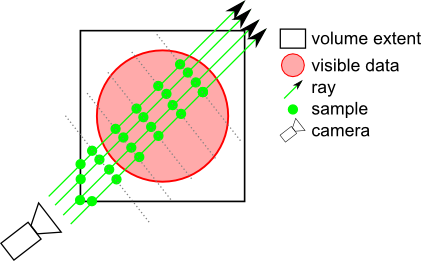
DATA_ALIGNED: Samples are located on planes perpendicular to one axis of the volume.
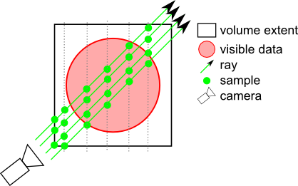
BOUNDARY_ALIGNED: Samples are located on shells aligned with the volume's internal "boundary". Each ray begins sampling at the first intersected voxel that has an alpha value >
opacityThreshold. This technique greatly decreases "slicing" artifacts even with a relatively small number of slices. It is strongly recommended to enable this mode when usingSoVolumeRenderingQuality.ambientOcclusion.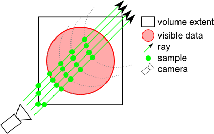
SMOOTH_BOUNDARY_ALIGNED: Similar to BOUNDARY_ALIGNED but uses a cubic interpolation to compute the boundary, giving smoother results when using
SoVolumeRenderingQuality.deferredLighting.NOTE: If an
SoVolumeGrouporSoProjectionnode applies to this node, the field is ignored and VIEW_ALIGNED is used.- Since:
- Open Inventor 9.1
-
opacityThreshold
Specifies a threshold opacity (alpha) value that defines voxels considered to be "solid" (non-transparent). Many volume data sets are composed of objects of interest floating in an approximately transparent "fog", depending on opacity values in the transfer function. Several effects like BOUNDARY_ALIGNED sampling, ambientOcclusion and deferredLighting need to locate the boundary between solid objects and ambient fog. This field defines a threshold in the range [0, 1]. Voxels are considered solid if their alpha value is greater than opacityThreshold.A value of 0.0 generally works well with a transfer function containing "binary" opacity (a transfer function with only fully transparent or fully opaque colors). If this is not the case, you should set this value according to your visualization parameters. Generally between 0.1 and 0.5.
Default is 0.1, Ignore low visibility voxels.
- Since:
- Open Inventor 9.3
-
stillScreenTileSize
Specifies the size of the screen tiles used for rendering. Default is (-1, -1), it means no screen tiling rendering. -
lighting
Deprecated.As of Open Inventor 8.5.0.0. Use SoVolumeRenderingQuality.lighting field instead.Indicates if lighting is required. Default is false.
NOTE: Better performance for lighting can be obtained using theSoVolumeRenderingQualitynode. UsingSoVolumeRenderingQuality, lighting is determined by the first light in the scene graph (similar to other geometry) and the lighting computation is done on the GPU (thereforeSoVolumeRenderingQualityrequires programmable shaders).Using the
lightingfield, lighting is determined by thelightDirectionfield and the lighting computation is done on the CPU. This requires RGBA textures to be loaded on the GPU which uses more texture memory and requires more time to modify the transfer function (color map) because textures must be reloaded. Note that activating or deactivating lighting will also normally force the textures to be recreated, which may be slow.NOTE: Only set the lighting field to true in
SoVolumeRenderingQualityorSoVolumeRender. Do not set bothlightingfields to true.Warning Deprecated since Open Inventor 8500. Use
SoVolumeRenderingQuality.lightingfield instead. -
lightDirection
Deprecated.As of Open Inventor 8.5.0.0. Use SoVolumeRenderingQuality.lighting field instead.Light direction (relative to the volume). The default is (-1,-1,-1). Only affects CPU computed lighting (i.e. when thelightingfield is true).Warning Deprecated since Open Inventor 8500. Use
SoVolumeRenderingQuality.lightingfield instead. -
lightIntensity
Deprecated.As of Open Inventor 8.5.0.0. Use SoVolumeRenderingQuality.lighting field instead.Light intensity in the range [0-1]. The default is 1. Only affects CPU computed lighting (i.e. when thelightingfield is true).Warning Deprecated since Open Inventor 8500. Use
SoVolumeRenderingQuality.lightingfield instead. -
viewAlignedSlices
Deprecated.As of Open Inventor 9.1.0.0. Use samplingAlignment field instead.Indicates if samples should be computed in a view-aligned manner. Default is true.NOTE: If an
SoVolumeIsosurface,SoVolumeRenderingQualityorSoProjectionnode applies to this node, this field is ignored and view-aligned samples are used.Warning Deprecated since Open Inventor 9100. Use samplingAlignment field instead.
Constructor Details
-
SoVolumeRender
public SoVolumeRender()Constructor.