You can choose one of three techniques for mapping the 2D texture space onto the 3D object space:
Use the default texture coordinates. The texture is applied in different ways for different shapes, as described later in this section.
For shapes derived from SoVertexShape SoVertexShape SoVertexShape , you can specify the texture coordinates explicitly. With this method, you create an SoTextureCoordinate2 SoTextureCoordinate2 SoTextureCoordinate2 node and specify a texture coordinate for each vertex in the shape.
Use one of the texture-coordinate functions to map the texture to the shape: SoTextureCoordinatePlane SoTextureCoordinateEnvironment
Techniques 1 and 3 are automatic, and hence easy to use. Technique 2 requires explicit coordinates generated by you and is thus harder to use but gives more explicit control. Each of these three techniques is described in detail in the following sections.
Inventor uses the same technique for generating default texture coordinates for any shape that is derived from SoVertexShape SoVertexShape SoVertexShape . First, it computes the bounding box of the object. Then, it uses the longest edge of the box as the horizontal (s) axis of the texture. It uses the next longest edge as the vertical (t) axis of the texture. The value of the s coordinate ranges from 0.0 to 1.0, from one end of the bounding box to the other. The value of t ranges from 0 to n, where n equals the ratio of the second longest side of the bounding box to the longest side (the effect is that the texture is applied to the longest side of the box, without distortion).
For shapes that are not derived from SoVertexShape SoVertexShape SoVertexShape , the default texture coordinates are generated differently for each shape. These shapes include SoCone SoCone SoCone , SoCube SoCube SoCube , SoCylinder SoCylinder SoCylinder , SoNurbsSurface SoNurbsSurface SoNurbsSurface , SoSphere SoSphere SoSphere , and SoText3 SoText3 SoText3 . Default texture mapping for each of these shapes is described in the following paragraphs.
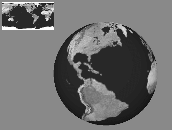
For example, if your scene graph contains an SoTexture2 SoTexture2 SoTexture2 node followed by an SoSphere SoSphere SoSphere node, the texture is applied to the sphere using default texture coordinates. The texture covers the entire surface of the sphere, wrapping counterclockwise from the back of the sphere (see Figure 7.12, “ Default Texture Mapping for SoSphere ”). The texture wraps around and connects to itself. A visible seam can result if the texture is nonrepeating.
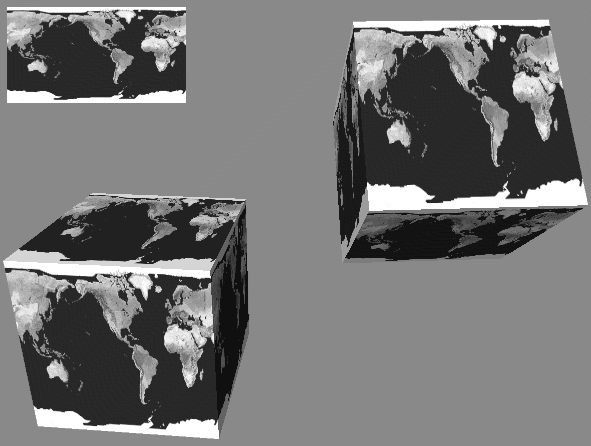
When a texture is applied to an SoCube SoCube SoCube using the default texture coordinates, the entire texture is applied to each face. On the front, back, right, and left sides of the cube, the texture is applied right-side up. On the top, the texture appears right-side up if you tilt the cube toward you. On the bottom, the texture appears right-side up if you tilt the cube away from you (see Figure 7.13, “ Default Texture Mapping for SoCube ”).
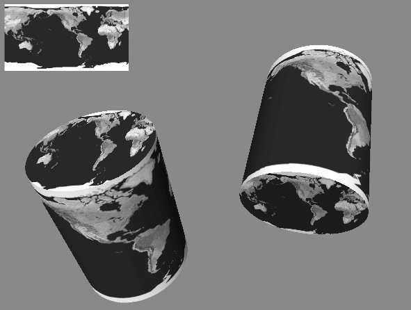
When a texture is applied to an SoCylinder SoCylinder SoCylinder using the default texture coordinates, the texture wraps around the sides in a counterclockwise direction, beginning at the -z axis. A circle cut from the center of the texture square is applied to the top and bottom of the cylinder. When you look at the cylinder from the +z axis, the texture on the top appears right-side up when the cylinder tips towards you. The texture on the bottom appears right-side up when the cylinder tips away from you (see Figure 7.14, “ Default Texture Mapping for SoCylinder ”).
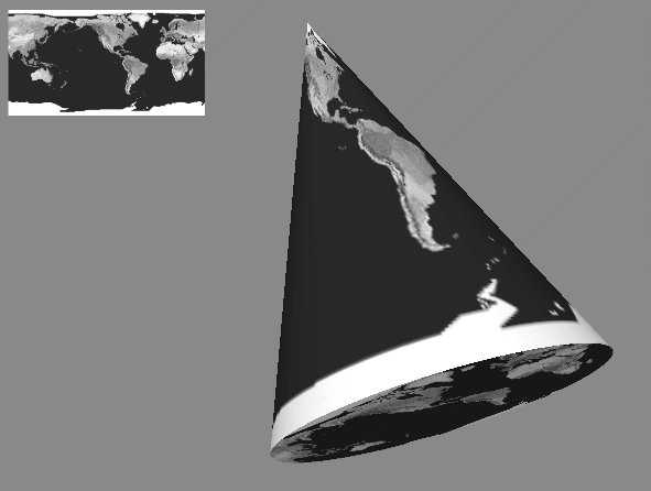
When a texture is applied to anSoCone SoCone SoCone using the default texture coordinates, the texture wraps counterclockwise around the sides of the cone, starting at the back of the cone. The texture wraps around and connects to itself. A visible seam can result if the texture is nonrepeating. A circle cut from the center of the texture square is applied to the bottom of the cone just as it is applied to the bottom of a cylinder (see Figure 7.15, “ Default Texture Mapping for SoCone ”).
![[Tip]](../images/tip.jpg) | |
Tip: Increasing the complexity of a textured cone is especially important because of the way the texture is mapped near the tip of the cone. |
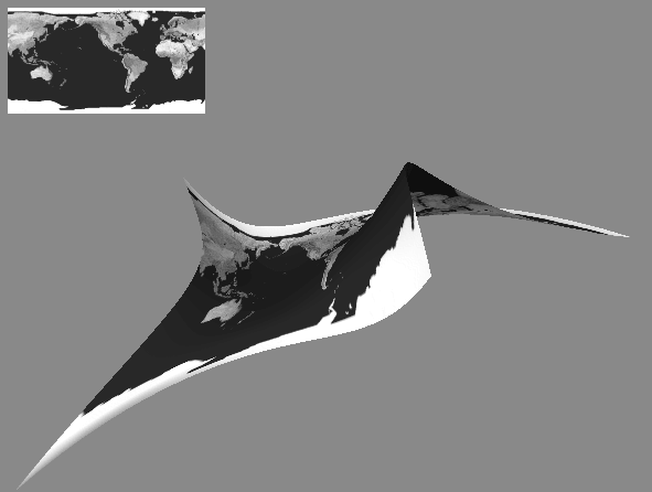
When a texture is applied to a NURBS surface using the default texture coordinates, the edges of the texture square are stretched to fit the NURBS patch (see Figure 7.16, “ Default Texture Mapping for SoNurbsSurface ”). A surface can be made up of many patches, like the teapot. If the NURBS surface is trimmed, so is the texture.
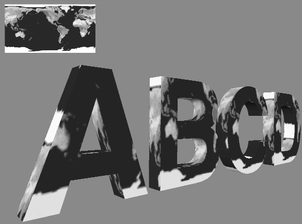
When a texture is applied to the front of an SoText3 SoText3 SoText3 surface using the default texture coordinates, texture coordinate (0,0) is at the text's origin. The distance from 0.0 to 1.0 in s and t texture coordinates is equal to the font size. For the sides of an SoText3 SoText3 SoText3 surface, using default texture mapping, the s coordinate extends forward along the text profile, starting with texture coordinate 0.0 at the back of the letter and increasing to the front. A font-size distance along the profile is a texture coordinate distance of 1.0. The t coordinates extend around the outline of the character clockwise in a similar fashion. (See Figure 7.17, “ Default Texture Mapping for SoText3 ”.)
Sometimes, you may want to explicitly specify the texture coordinates for each vertex of an object. In this case, create an SoTextureCoordinate2 SoTextureCoordinate2 SoTextureCoordinate2 node and specify the set of 2D texture coordinates to be applied to the vertices of the shape.
When you use this technique, you must specify a texture coordinate for each vertex in the shape. The coordinates are specified in pairs: the s coordinate followed by the t coordinate.
Example 7.3, “ Specifying Texture Coordinates Explicitly ” shows specifying texture coordinates explicitly. It uses an SoTextureCoordinateBinding SoTextureCoordinateBinding SoTextureCoordinateBinding node to index into the texture-coordinates list.
Example 7.3. Specifying Texture Coordinates Explicitly
#include <Inventor/Xt/SoXt.h>
#include <Inventor/Xt/viewers/SoXtExaminerViewer.h>
#include <Inventor/nodes/SoCoordinate3.h>
#include <Inventor/nodes/SoFaceSet.h>
#include <Inventor/nodes/SoNormal.h>
#include <Inventor/nodes/SoNormalBinding.h>
#include <Inventor/nodes/SoSeparator.h>
#include <Inventor/nodes/SoTexture2.h>
#include <Inventor/nodes/SoTextureCoordinate2.h>
#include <Inventor/nodes/SoTextureCoordinateBinding.h>

main(int , char **argv)
{
   Widget myWindow = SoXt::init(argv[0]);
   if(myWindow == NULL) exit(1);

   SoSeparator *root = new SoSeparator;
   root->ref();

   // Choose a texture
   SoTexture2 *brick = new SoTexture2;
   root->addChild(brick);
   brick->filename.setValue("brick.1.rgb");

   // Define the square's spatial coordinates
   SoCoordinate3 *coord = new SoCoordinate3;
   root->addChild(coord);
   coord->point.set1Value(0, SbVec3f(-3, -3, 0));
   coord->point.set1Value(1, SbVec3f( 3, -3, 0));
   coord->point.set1Value(2, SbVec3f( 3,  3, 0));
   coord->point.set1Value(3, SbVec3f(-3,  3, 0));

   // Define the square's normal
   SoNormal *normal = new SoNormal;
   root->addChild(normal);
   normal->vector.set1Value(0, SbVec3f(0, 0, 1));

   // Define the square's texture coordinates
   SoTextureCoordinate2 *texCoord = new SoTextureCoordinate2;
   root->addChild(texCoord);
   texCoord->point.set1Value(0, SbVec2f(0, 0));
   texCoord->point.set1Value(1, SbVec2f(1, 0));
   texCoord->point.set1Value(2, SbVec2f(1, 1));
   texCoord->point.set1Value(3, SbVec2f(0, 1));

   // Define normal and texture coordinate bindings
   SoNormalBinding *nBind = new SoNormalBinding;
   SoTextureCoordinateBinding *tBind =
            new SoTextureCoordinateBinding;
   root->addChild(nBind);
   root->addChild(tBind);
   nBind->value.setValue(SoNormalBinding::OVERALL);
   tBind->value.setValue
            (SoTextureCoordinateBinding::PER_VERTEX);

   // Define a FaceSet
   SoFaceSet *myFaceSet = new SoFaceSet;
   root->addChild(myFaceSet);
   myFaceSet->numVertices.set1Value(0, 4);

   SoXtExaminerViewer *myViewer =
            new SoXtExaminerViewer(myWindow);
   myViewer->setSceneGraph(root);
   myViewer->setTitle("Texture Coordinates");
   myViewer->show();

   SoXt::show(myWindow);
   SoXt::mainLoop();
}
using OIV.Inventor.Nodes;
using OIV.Inventor.Win;
using OIV.Inventor.Win.Viewers;
using OIV.Inventor;

namespace _07_2_TextureCoordinates
{
    public partial class MainForm : Form
    {
        SoWinExaminerViewer myViewer;

        public MainForm()
        {
            InitializeComponent();
            CreateSample();
        }

        public void CreateSample()
        {
            SoSeparator root = new SoSeparator();

            // Choose a texture
            SoTexture2 brick = new SoTexture2();
            root.AddChild(brick);
            brick.filename.SetValue("../../../../../data/brick.1.png");

            // Using the new SoVertexProperty node is more efficient
            SoVertexProperty myVertexProperty = new SoVertexProperty();

            // Define the square's spatial coordinates
            myVertexProperty.vertex.Set1Value(0, new SbVec3f(-3, -3, 0));
            myVertexProperty.vertex.Set1Value(1, new SbVec3f(3, -3, 0));
            myVertexProperty.vertex.Set1Value(2, new SbVec3f(3, 3, 0));
            myVertexProperty.vertex.Set1Value(3, new SbVec3f(-3, 3, 0));

            // Define the square's normal
            myVertexProperty.normal.Set1Value(0, new SbVec3f(0, 0, 1));

            // Define the square's texture coordinates
            myVertexProperty.texCoord.Set1Value(0, new SbVec2f(0, 0));
            myVertexProperty.texCoord.Set1Value(1, new SbVec2f(1, 0));
            myVertexProperty.texCoord.Set1Value(2, new SbVec2f(1, 1));
            myVertexProperty.texCoord.Set1Value(3, new SbVec2f(0, 1));

            // Define normal binding
            myVertexProperty.normalBinding.SetValue(
                    (int)SoNormalBinding.Bindings.OVERALL);

            // Define a FaceSet
            SoFaceSet myFaceSet = new SoFaceSet();
            root.AddChild(myFaceSet);
            myFaceSet.numVertices.Set1Value(0, 4);

            myFaceSet.vertexProperty.SetValue(myVertexProperty);

            myViewer = new SoWinExaminerViewer(this, "", true,
                SoWinFullViewer.BuildFlags.BUILD_ALL, SoWinViewer.Types.BROWSER);
            myViewer.SetSceneGraph(root);
            myViewer.SetTitle("Texture Coordinates");

            // In Inventor 2.1, if the machine does not have hardware texture
            // mapping, we must override the default drawStyle to display textures.
            myViewer.SetDrawStyle(SoWinViewer.DrawTypes.STILL,
                           SoWinViewer.DrawStyles.VIEW_AS_IS);
        }
    }
}
import tools.*;

import com.openinventor.inventor.awt.*;
import com.openinventor.inventor.nodes.*;
import com.openinventor.inventor.*;
import com.openinventor.util.Scene.DrawStyle;

import java.awt.*;

public class Main extends DemoInventor
{

  public static void main(String[] args)
  {
    Main applet = new Main();
    DemoInventor.isAnApplet = false;
    applet.start();
    demoMain(applet, "Texture Coordinates");
  }

  public void start()
  {
    super.start();

    // Choose a texture
    SoTexture2 brick = new SoTexture2();
    brick.filename.setValue(m_prefix + "../../../../data/textures/rgb/brick.1.rgb");

    SoVertexProperty myVertexProperty = new SoVertexProperty();

    // Define the square's spatial coordinates
    myVertexProperty.vertex.set1Value(0, new SbVec3f(-3, -3, 0));
    myVertexProperty.vertex.set1Value(1, new SbVec3f(3, -3, 0));
    myVertexProperty.vertex.set1Value(2, new SbVec3f(3, 3, 0));
    myVertexProperty.vertex.set1Value(3, new SbVec3f(-3, 3, 0));

    // Define the square's normal
    myVertexProperty.normal.set1Value(0, new SbVec3f(0, 0, 1));

    // Define the square's texture coordinates
    myVertexProperty.texCoord.set1Value(0, new SbVec2f(0, 0));
    myVertexProperty.texCoord.set1Value(1, new SbVec2f(1, 0));
    myVertexProperty.texCoord.set1Value(2, new SbVec2f(1, 1));
    myVertexProperty.texCoord.set1Value(3, new SbVec2f(0, 1));

    // Define normal binding
    myVertexProperty.normalBinding.setValue(SoNormalBinding.Bindings.OVERALL);

    // Define a FaceSet
    SoFaceSet myFaceSet = new SoFaceSet();
    myFaceSet.numVertices.set1Value(0, 4);

    myFaceSet.vertexProperty.setValue(myVertexProperty);

    SoSeparator root = new SoSeparator();
    { // Assemble scene graph
      root.addChild(brick);
      root.addChild(myFaceSet);
    }

    SwSimpleViewer myViewer = new SwSimpleViewer();
    myViewer.setSceneGraph(root);

    // In Inventor 2.1, if the machine does not have hardware texture
    // mapping, we must override the default drawStyle to display textures.
    myViewer.getArea().setDrawStyle(SwActiveArea.STILL, DrawStyle.VIEW_AS_IS);

    setLayout(new BorderLayout());
    add(myViewer, BorderLayout.CENTER);
  }
}
A third way to map texture coordinates onto an object is through the use of a texture-coordinate function. A texture-coordinate function defines the texture coordinates for an object based on the position of each vertex in the object. Each texture-coordinate function uses a different algorithm for calculating the texture coordinates, as described in detail in the following subsections. These functions allow you to specify texture mapping in a general way, without requiring you to define explicit texture coordinates. The texture-coordinate function ignores the current texture coordinates specified by an SoTextureCoordinate2 SoTextureCoordinate2 SoTextureCoordinate2 node.
Inventor includes two texture-coordinate functions:
SoTextureCoordinatePlane SoTextureCoordinatePlane SoTextureCoordinatePlane | projects a texture map through a plane. |
SoTextureCoordinateEnvironment SoTextureCoordinateEnvironment SoTextureCoordinateEnvironment | specifies that objects should look as if they reflect their environment (also known as reflection mapping or environment mapping). |
To use the default texture coordinates (in effect, to “turn off” the effect of any previous texture-coordinate node in the scene graph without using a separator), use the SoTextureCoordinateDefault SoTextureCoordinateDefault SoTextureCoordinateDefault node.
SoTextureCoordinatePlane SoTextureCoordinatePlane SoTextureCoordinatePlane , probably the most commonly used texture-coordinate function, projects a texture plane onto a shape object, as shown in Figure B.14, “ Plate 14 ”. You define an s and a t direction, which are used to define a plane for the texture. The texture coordinate (s) is then defined by the following equation, where coord is a coordinate in the object:

The fields for SoTextureCoordinatePlane SoTextureCoordinatePlane SoTextureCoordinatePlane are as follows:
directionS (SoSFVec3f) | projection direction of s coordinate (default = 1.0, 0.0, 0.0) |
directionT (SoSFVec3f) | projection direction of t coordinate (default = 0.0, 1.0, 0.0) |
The length of the direction vector equals the repeat interval of the texture (see Example 7.4, “ Using SoTextureCoordinatePlane ”).
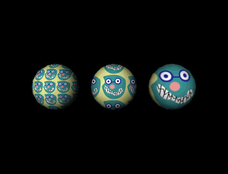
Example 7.4, “ Using SoTextureCoordinatePlane ” shows the use ofSoTextureCoordinatePlane SoTextureCoordinatePlane SoTextureCoordinatePlane (see Figure 7.18, “ SoTextureCoordinatePlane with Different Repeat Frequencies”). It draws three texture-mapped spheres, each with a different repeat frequency as defined by the fields of the SoTextureCoordinatePlane SoTextureCoordinatePlane SoTextureCoordinatePlane node.
Example 7.4. Using SoTextureCoordinatePlane
#include <Inventor/nodes/SoMaterial.h>
#include <Inventor/nodes/SoSeparator.h>
#include <Inventor/nodes/SoSphere.h>
#include <Inventor/nodes/SoTexture2.h>
#include <Inventor/nodes/SoTexture2Transform.h>
#include <Inventor/nodes/SoTextureCoordinatePlane.h>
#include <Inventor/nodes/SoTranslation.h>

#include <Inventor/Xt/SoXt.h>
#include <Inventor/Xt/viewers/SoXtExaminerViewer.h>

main(int , char **argv)
{
   Widget myWindow = SoXt::init(argv[0]);
   if(myWindow == NULL) exit(1);

   SoSeparator *root = new SoSeparator;
   root->ref();

   // Choose a texture.
   SoTexture2 *faceTexture = new SoTexture2;
   root->addChild(faceTexture);
   faceTexture->filename.setValue("sillyFace.rgb");
   // Make the diffuse color pure white
   SoMaterial *myMaterial = new SoMaterial;
   myMaterial->diffuseColor.setValue(1,1,1);
   root->addChild(myMaterial);

   // This texture2Transform centers the texture about (0,0,0)
   SoTexture2Transform *myTexXf = new SoTexture2Transform;
   myTexXf->translation.setValue(.5,.5);
   root->addChild(myTexXf);

   // Define a texture coordinate plane node.  This one will
   // repeat with a frequency of two times per unit length.
   // Add a sphere for it to affect.
   SoTextureCoordinatePlane *texPlane1 = new
             SoTextureCoordinatePlane;
   texPlane1->directionS.setValue(SbVec3f(2,0,0));
   texPlane1->directionT.setValue(SbVec3f(0,2,0));
   root->addChild(texPlane1);
   root->addChild(new SoSphere);

   // A translation node for spacing the three spheres.
   SoTranslation *myTranslation = new SoTranslation;
   myTranslation->translation.setValue(2.5,0,0);

   // Create a second sphere with a repeat frequency of 1.
   SoTextureCoordinatePlane *texPlane2 = new
            SoTextureCoordinatePlane;
   texPlane2->directionS.setValue(SbVec3f(1,0,0));
   texPlane2->directionT.setValue(SbVec3f(0,1,0));
   root->addChild(myTranslation);
   root->addChild(texPlane2);
   root->addChild(new SoSphere);

   // The third sphere has a repeat frequency of .5
   SoTextureCoordinatePlane *texPlane3 = new
            SoTextureCoordinatePlane;
   texPlane3->directionS.setValue(SbVec3f(.5,0,0));
   texPlane3->directionT.setValue(SbVec3f(0,.5,0));
   root->addChild(myTranslation);
   root->addChild(texPlane3);
   root->addChild(new SoSphere);

   SoXtExaminerViewer *myViewer = new SoXtExaminerViewer(myWindow);
   myViewer->setSceneGraph(root);
   myViewer->setTitle("Texture Coordinate Plane");
   myViewer->show();

   SoXt::show(myWindow);
   SoXt::mainLoop();
}
using OIV.Inventor.Nodes;
using OIV.Inventor.Win;
using OIV.Inventor.Win.Viewers;
using OIV.Inventor;

namespace _07_3_TextureFunction
{
    public partial class MainForm : Form
    {
        SoWinExaminerViewer myViewer;

        public MainForm()
        {
            InitializeComponent();
            CreateSample();
        }

        public void CreateSample()
        {
            SoSeparator root = new SoSeparator();

            // Choose a texture.
            SoTexture2 faceTexture = new SoTexture2();
            root.AddChild(faceTexture);
            faceTexture.filename.SetValue("../../../../../data/sillyFace.png");

            // Make the diffuse color pure white
            SoMaterial myMaterial = new SoMaterial();
            myMaterial.diffuseColor.SetValue(1, 1, 1);
            root.AddChild(myMaterial);

            // This texture2Transform centers the texture about (0,0,0)
            SoTexture2Transform myTexXf = new SoTexture2Transform();
            myTexXf.translation.SetValue(.5f, .5f);
            root.AddChild(myTexXf);

            // Define a texture coordinate plane node.  This one will
            // repeat with a frequency of two times per unit length.
            // Add a sphere for it to affect.
            SoTextureCoordinatePlane texPlane1 = new SoTextureCoordinatePlane();
            texPlane1.directionS.SetValue(new SbVec3f(2, 0, 0));
            texPlane1.directionT.SetValue(new SbVec3f(0, 2, 0));
            root.AddChild(texPlane1);
            root.AddChild(new SoSphere());

            // A translation node for spacing the three spheres.
            SoTranslation myTranslation = new SoTranslation();
            myTranslation.translation.SetValue(2.5f, 0f, 0f);

            // Create a second sphere with a repeat frequency of 1.
            SoTextureCoordinatePlane texPlane2 = new SoTextureCoordinatePlane();
            texPlane2.directionS.SetValue(new SbVec3f(1, 0, 0));
            texPlane2.directionT.SetValue(new SbVec3f(0, 1, 0));
            root.AddChild(myTranslation);
            root.AddChild(texPlane2);
            root.AddChild(new SoSphere());

            // The third sphere has a repeat frequency of .5
            SoTextureCoordinatePlane texPlane3 = new SoTextureCoordinatePlane();
            texPlane3.directionS.SetValue(new SbVec3f(.5f, 0f, 0f));
            texPlane3.directionT.SetValue(new SbVec3f(0f, .5f, 0f));
            root.AddChild(myTranslation);
            root.AddChild(texPlane3);
            root.AddChild(new SoSphere());

            myViewer = new SoWinExaminerViewer(this, "", true,
                SoWinFullViewer.BuildFlags.BUILD_ALL, SoWinViewer.Types.BROWSER);
            myViewer.SetSceneGraph(root);
            myViewer.SetTitle("Texture Coordinate Plane");

            // In Inventor 2.1, if the machine does not have hardware texture
            // mapping, we must override the default drawStyle to display textures.
            myViewer.SetDrawStyle(SoWinViewer.DrawTypes.STILL,
                           SoWinViewer.DrawStyles.VIEW_AS_IS);
        }
    }
}
import tools.*;

import com.openinventor.inventor.awt.*;
import com.openinventor.inventor.nodes.*;
import com.openinventor.inventor.*;
import com.openinventor.util.Scene.DrawStyle;

import java.awt.*;

public class Main extends DemoInventor
{

  public static void main(String[] args)
  {
    Main applet = new Main();
    applet.isAnApplet = false;
    applet.start();
    demoMain(applet, "Texture Coordinate Plane");
  }

  public void start()
  {
    super.start();

    // Choose a texture.
    SoTexture2 faceTexture = new SoTexture2();
    faceTexture.filename.setValue(m_prefix + "../../../../data/textures/rgb/sillyFace.rgb");

    // Make the diffuse color pure white
    SoMaterial myMaterial = new SoMaterial();
    myMaterial.diffuseColor.setValue(1, 1, 1);

    // This texture2Transform centers the texture about (0,0,0)
    SoTexture2Transform myTexXf = new SoTexture2Transform();
    myTexXf.translation.setValue(.5f, .5f);

    // Define a texture coordinate plane node. This one will
    // repeat with a frequency of two times per unit length.
    // Add a sphere for it to affect.
    SoTextureCoordinatePlane texPlane1 = new SoTextureCoordinatePlane();
    texPlane1.directionS.setValue(new SbVec3f(2, 0, 0));
    texPlane1.directionT.setValue(new SbVec3f(0, 2, 0));

    // A translation node for spacing the three spheres.
    SoTranslation myTranslation = new SoTranslation();
    myTranslation.translation.setValue(2.5f, 0, 0);

    // Create a second sphere with a repeat frequency of 1.
    SoTextureCoordinatePlane texPlane2 = new SoTextureCoordinatePlane();
    texPlane2.directionS.setValue(new SbVec3f(1, 0, 0));
    texPlane2.directionT.setValue(new SbVec3f(0, 1, 0));

    // The third sphere has a repeat frequency of .5
    SoTextureCoordinatePlane texPlane3 = new SoTextureCoordinatePlane();
    texPlane3.directionS.setValue(new SbVec3f(.5f, 0, 0));
    texPlane3.directionT.setValue(new SbVec3f(0, .5f, 0));

    SoSeparator root = new SoSeparator();
    { // Assemble scene graph
      root.addChild(faceTexture);
      root.addChild(myMaterial);
      root.addChild(myTexXf);
      root.addChild(texPlane1);
      root.addChild(new SoSphere());
      root.addChild(myTranslation);
      root.addChild(texPlane2);
      root.addChild(new SoSphere());
      root.addChild(myTranslation);
      root.addChild(texPlane3);
      root.addChild(new SoSphere());
    }

    SwSimpleViewer myViewer = new SwSimpleViewer();
    myViewer.setSceneGraph(root);

    // In Inventor 2.1, if the machine does not have hardware texture
    // mapping, we must override the default drawStyle to display textures.
    myViewer.getArea().setDrawStyle(SwActiveArea.STILL, DrawStyle.VIEW_AS_IS);

    setLayout(new BorderLayout());
    add(myViewer, BorderLayout.CENTER);
  }
}
The SoTextureCoordinateEnvironment SoTextureCoordinateEnvironment SoTextureCoordinateEnvironment node specifies that subsequent objects should reflect their environment, just as a shiny round Christmas ornament reflects its surroundings. For best results, the texture map specified should be a spherical reflection map. See the OpenGL Programming Guide, Chapter 9, for tips on how to create a spherical reflection map.
When SoTextureCoordinateEnvironment SoTextureCoordinateEnvironment SoTextureCoordinateEnvironment is used, a calculation is made at each vertex of the polygon to determine where a vector from the viewpoint to the vertex would be reflected. This reflection point defines the texture coordinate for that point on the polygon. See Figure B.16, “ Plate 16 ” and Figure B.17, “ Plate 17 ”.
Because of the way environment mapping is implemented in OpenGL, environment maps are accurate only if the camera does not move relative to the environment being reflected.
